
DCO configuration using CMIS AppSel
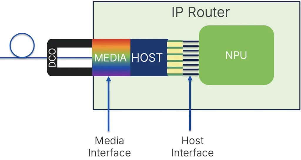
In this blog we will take a look at the management of Digital Coherent Optics across the different layers from low-level pluggable component to multi-layer automation.
Routed Optical Networking
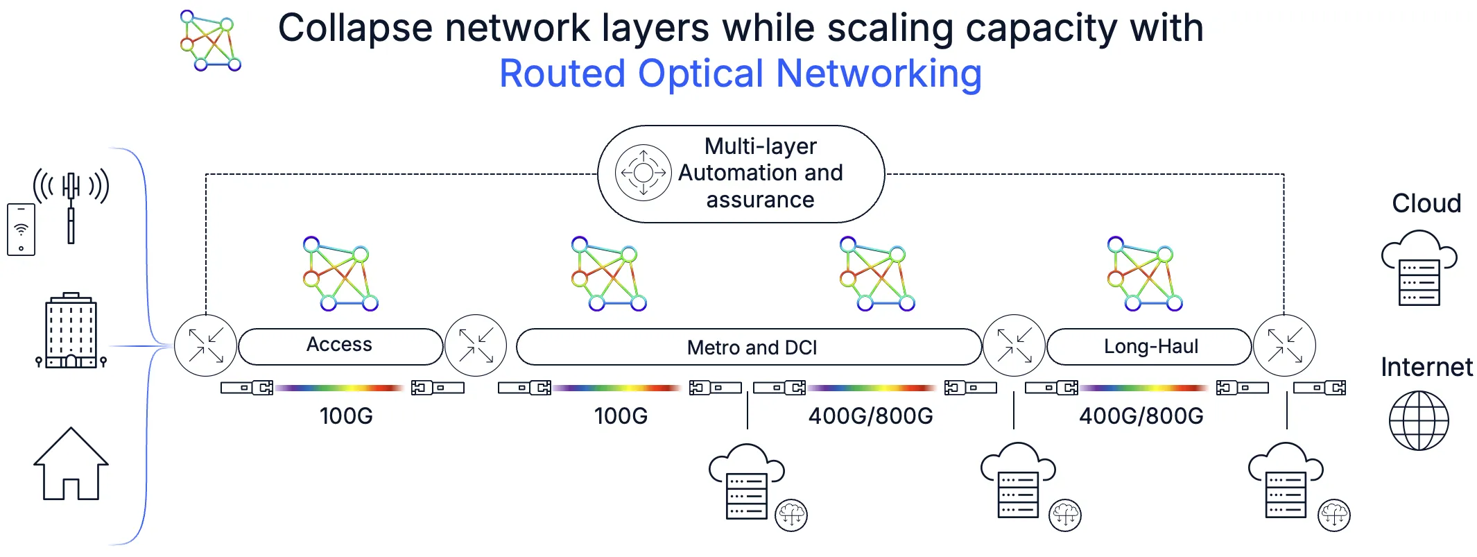
Routed Optical Networking introduced by Cisco in 2020 introduced a fundamental shift in how IP+Optical networks are built. Collapsing previously disparate network layers and services into a single unified domain, Routed Optical Networking simplifies operations and lowers overall network TCO. More information on Routed Optical Networking can be found at the following locations:
- https://www.cisco.com/c/en/us/solutions/service-provider/routed-optical-networking.html
- Routed Optical Networking HLD
You an also view these additional blogs covering Routed Optical Networking pluggables
- Monitoring Digital Coherent Optics in IOS-XR
- Managing OpenZR+ and OIF ZR transceivers on Cisco routers using OpenConfig
- Path forward to any plug in any host
Pluggable Digital Coherent Optics Overview
One of the foundations of Routed Optical Networking is the use of small form factor pluggable digital coherent optics. These optics can be used in a wide variety of network applications, reducing CapEx/OpEx cost and reducing complexity vs. using traditional external transponder equipment. They along with advanced automation and a simplified routing layer contirbute to our Agile Services Networking architecture.
OIF, OpenZR+, and OpenROADM Standards for Digital Coherent Optics
The networking industry saw a point to improve network efficiency by shifting coherent DWDM functions from dedicated integrated hardware to pluggable optics. Technology advancements have shrunk the DCO components into the standard QSFP-DD and OSFP form factors, meaning no specialized hardware and the ability to use the highest capacity routers available today. Today pluggable digital coherent optics can be used in the same ports as the highest speed non-DCO transceivers.
Two industry optical standards originally emerged to cover a variety of use cases for 400G DCO. The OIF created the 400ZR specification, https://www.oiforum.com/technical-work/hot-topics/400zr-2 as a 400G interopable standard for metro reach coherent optics covering distances up to 120km. The industry saw the benefit of the approach, but wanted to cover longer distances and have flexibility in wavelength rates, so the OpenZR+ MSA was created, https://www.openzrplus.org.
800G DCO standards
Standards for 800G were begun around 2023 with the release of production 800G DCO in 2026. The 800G standards released by the OIF include 800ZR. 800ZR being similar to 400ZR covering reach up to 120km with standard baud rate, modulation, and FEC. OpenROADM, another industry consortium, created additional flexible standards for 800G line side modes. These include higher baud rate modes up to 131Gbaud and interoperable PCS (Probabilistic Constellation Shaping) modulation. The original OpenZR+ MSA chose to adopt the OpenROADM standards for 800G. Modules considered to be “800G ZR+” typically support the OpenROADM 800G modes along with the 400G OpenZR+ modes.
100G ZR
Within the last three years we’ve also seen the introduction of QSFP28 100G tunable DWDM DCO. The previous OpenZR+ 400G-ZR+ standard covered 100G modes, but still relied on using a QSFP-DD port. QSFP28 allows the use of the optics in many platforms which do not contain QSFP-DD ports. There is no standard govering 100G DCO, but they all utilize the following line side mode with QPSK modulation, ITU-T G.709.2 SC-FEC, and a baud rate of 30.07GBaud.
Specifications table
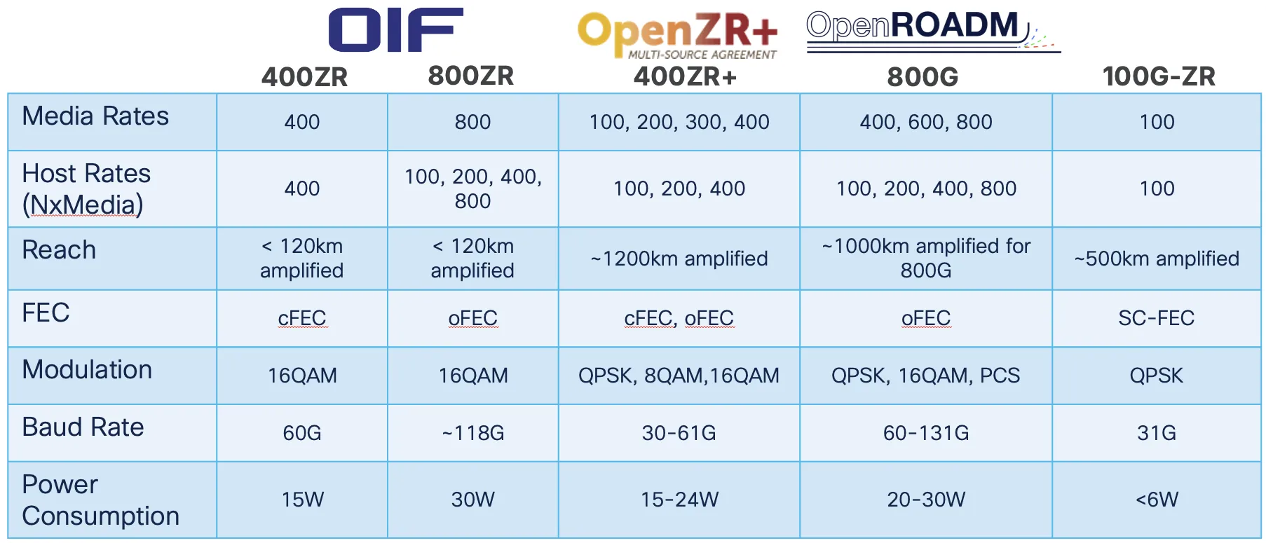
While most optics support industry standards, optics vendors also have proprietary modes used to support specialized applications or additional reach.
Cisco standards-based pluggable DCO
The following part numbers are used for Cisco Digital Coherent Optics as of June 2026 in order of release
| Part | Standards | Description |
|---|---|---|
| QDD-400G-ZR-S | 400ZR | OIF 400ZR only |
| QDD-400G-ZRP-S | 400ZR,OpenZR+ | Supports both standards |
| DP04QSDD-HE0 | 400ZR,OpenZR+ High-Power (Bright) | +1 dBm, supports both standards |
| DP04QSDD-ULH-A1 | OpenZR+ | +1 dBm, C-band |
| DP04QSDD-LLH-A1 | OpenZR+ | -2 dBm, L-band |
| DP08QSDD-ZRA-A2 | 800ZR | OIF 800ZR only |
| DP08QSDD-ZRB-A2 | 400G OpenZR+,800ZR,OpenROADM | C-band |
| DP08QSDD-LRB-A2 | 400G OpenZR+,800ZR,OpenROADM | L-band |
| DP01QS28-E20 | 100G-ZR | -6dBm, standard temp, 300km |
| DP01QS28-E25 | 100G-ZR | -6dBm, extended temp, 300km |
| DP01QS28-MX2-A1 | 100G-ZR | 0 dBm, extended temp, 500km |
Management domains
When we look at potential management domains it depends on the deployment model. A traditional photonic network built from active
optical components may be deployed, requiring the management of those elements and photonic circuits built across them. Networks using
point to point circuits across dark fiber or passive mux/demux may only manage the DCO endpoints.
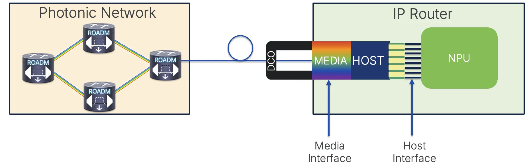
Photonic network management
Photonic networks are typically still closed ecosystems and managed by vendor-supplied management systems. However, there are now standards based APIs used
on the northbound side of the optical controllers or NMS managing those systems. TAPI has become the defacto standard for most optical
controllers. More information on TAPI can be found at https://github.com/Open-Network-Models-and-Interfaces-ONMI/TAPI
Pluggable DCO management
Pluggable Digital Coherent Optics detail
Digital Coherent Optics are complex technology. In this blog we will not go into low level detail of the inner workings of the optics, but look at some of the basic components to help understand where specific performance measurement data is derived from and how best to monitor the optics.
Component diagram
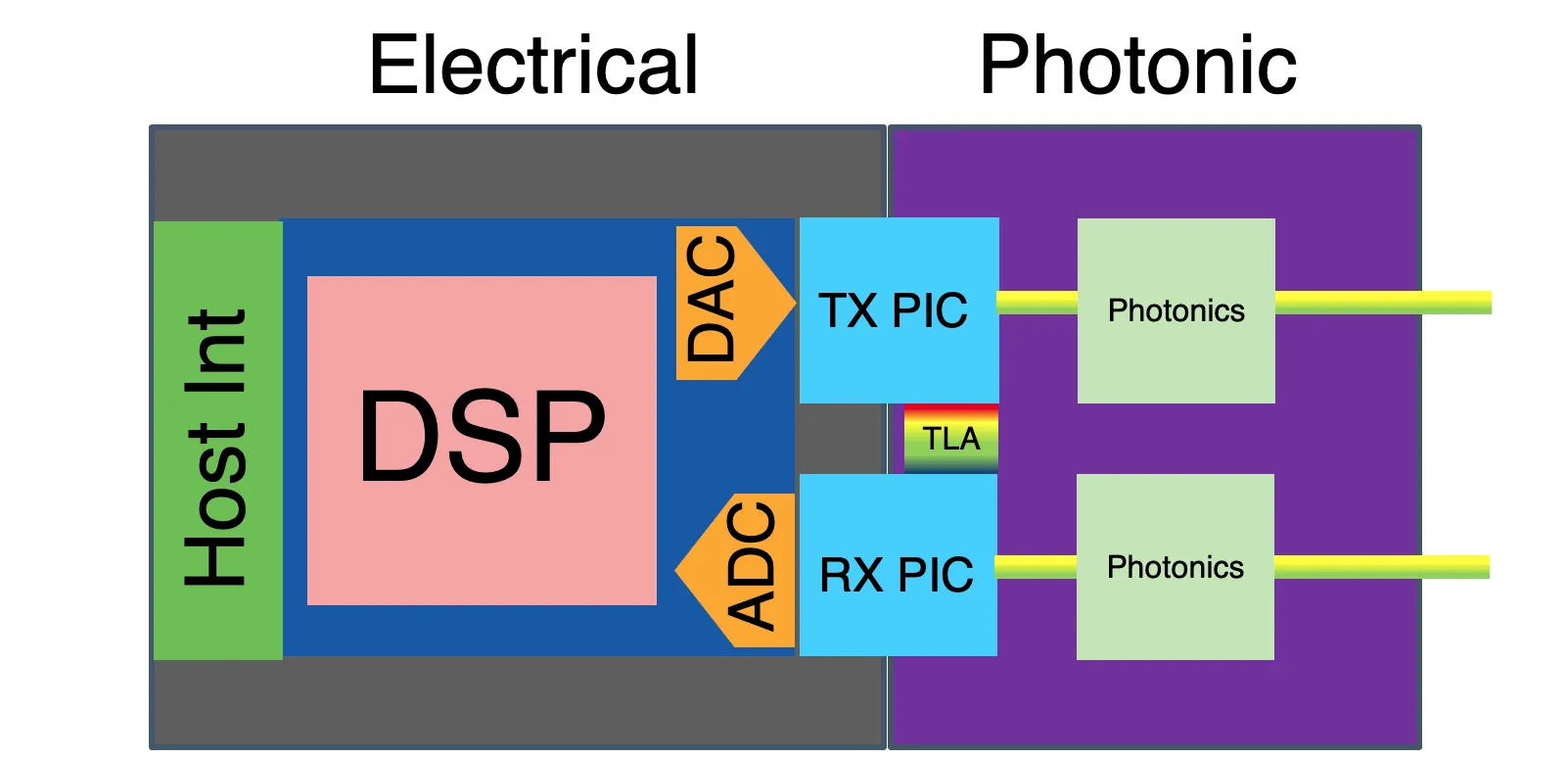
Component packaging
On modern DCO like Cisco’s ZR/ZR+ optics multiple elements are co-packaged leading to simpler design and greater power efficiency.
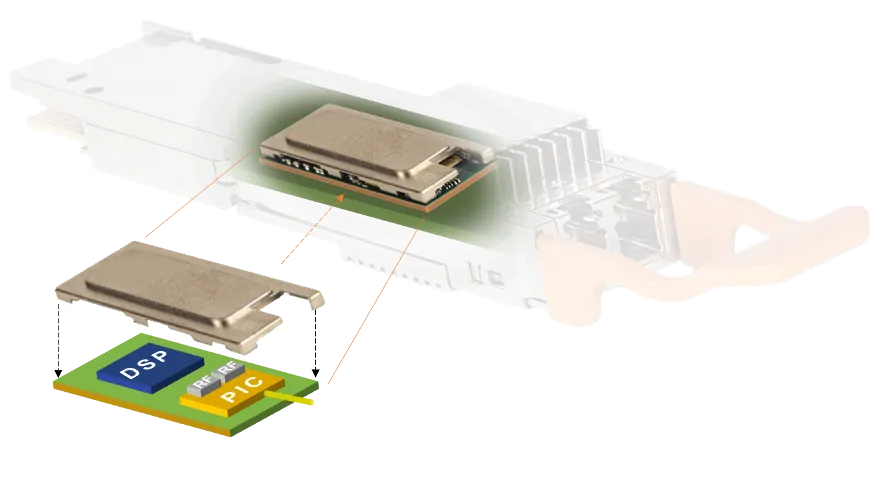
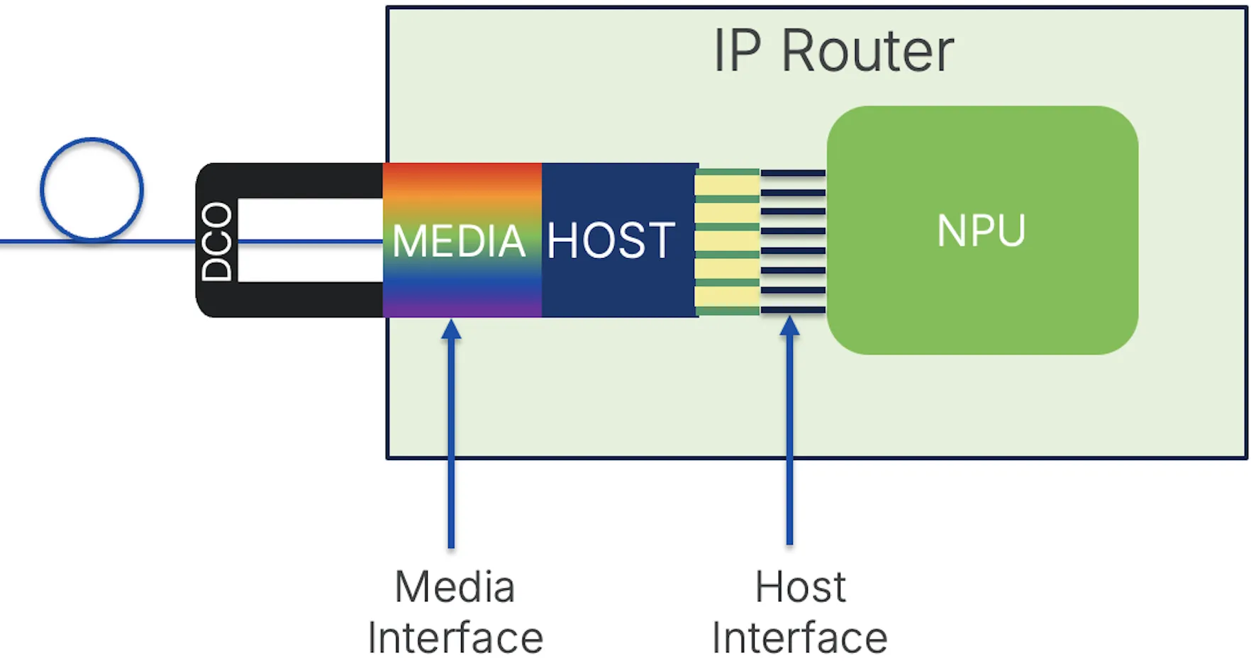
Host and Media interfaces
Pluggable transceivers have two distinct sides. One side is the “host” side connecting to a host platform via electrical pins and the “media” side connecting to the physical media. In the case of a DCO this would be single mode fiber.
OIF Common Management Interface Specification (CMIS)

CMIS was originally created by the QSFP-DD MSA to create a modern way to manage QSFP-DD optics. The first
published version of CMIS by the QSFP-DD MSA was 3.0 in 2018. Starting with CMIS 5.2, published in April 2022, CMIS became an OIF project utilizing the OIF structure for Implementation Agreement definition. The current version of CMIS is 5.3, with 5.4 publication happening in 2026. The goal of CMIS is stated in the introduction of the specification.
This specification, CMIS, has been developed to allow host and module software implementers to utilize a8
common code base across a variety of form factors and across a variety of transmission module1 capabilities,9
and to foster the possibility of vendor agnostic management for standardized module functions.
What does CMIS cover?
CMIS covers the core management aspects of the pluggable transceivers. The current CMIS specification covers the following major areas:
- Advertisement and selection of an “application”
- Diagnostic monitoring via standard registers
- Control and monitoring of optics state through a state machine based control paradigm (DPSM)
- Firmware management
- Optics security
The configuration of the appropriate mode for the host and
media side of the optic is one function we’ll expand on.
OIF Coherent CMIS (C-CMIS)
In addition to the base CMIS document, there are companion documents providing
extended capabilities for specific optics types or functionality. Coherent optics
have their own unique properties requiring additional standards. C-CMIS extends CMIS with the
following functionality as of C-CMIS 1.4:
- Define DCO PM data fields and units
- Define standard registers for retrieval of DCO PM data
- Retrieval of DCO properties for a specific Application (OSNR threshold, PMD threshold, etc.)
Optics and host support for CMIS and C-CMIS
Optics will typically support a single version of CMIS based on their release date and capabilities. A host will typically support several versions of CMIS. CMIS is meant to be backwards compatible with previous versions, so a host with CMIS
5.3 support should work with an optic supporting an earlier version of CMIS.
Latest versions of CMIS and C-CMIS Implementation Agreements
The latest version of the CMIS IA as of this publishing June 2026 is 5.3. Version 5.4 is anticipated to be published within
2026.
📥 https://www.oiforum.com/wp-content/uploads/OIF-CMIS-05.3.pdf
The latest version of the C-CMIS IA as of this publishing June 2026 is 1.4. Version 1.5 is anticipated to be published within
2026.
📥 https://www.oiforum.com/wp-content/uploads/OIF-C-CMIS-01.4.pdf
SNIA (Storage Networking Industry Association) SFF (Small Form Factor) TWG (Technical Work Group)
The SFF as a technical organization has existed since 1990, creating
interoperable standards for a wide variety of technologies across storage and
networking. SFF-8636 is a precursor to CMIS and is the management protocol
used for QSFP optics. It is still used in conjunction with CMIS in managing
those optics types. SFP+ and SFP optics are similarly managed using SFF
specifications.
Role of the SFF TWG
Not specific to DCO, the SFF TWG publishes a set of standards-based host and
media ID values used to configure optics. These are found in SFF-8024, the SFF
Module Management Reference Code Tables. Separate tables are published for
host electrical standards and media based on the type of physical medium.
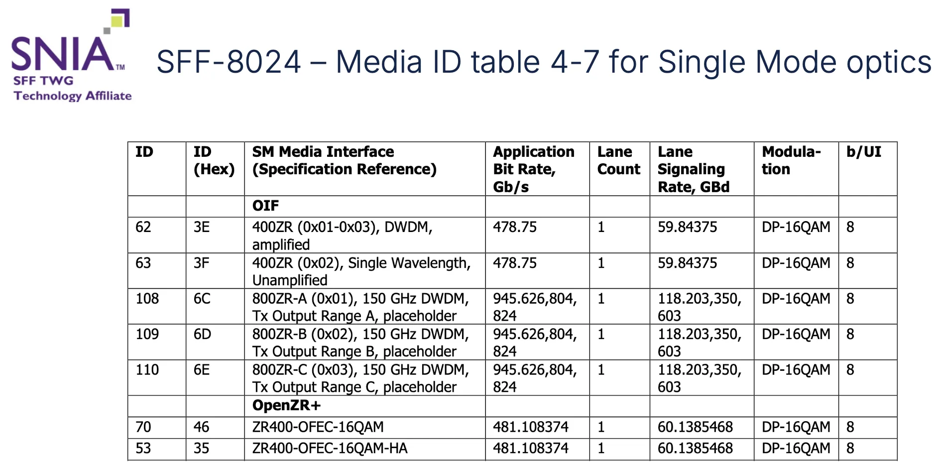
Since DCO utilize single-mode fiber, the table of interest with modes covering
DCO are found in the table for Single-Mode Optics.
The SFF-8024 tables contain 8-bit identifiers. In the CMIS 5.4 release there is
an option to use an expanded interface ID format, using a 4-bit Group ID (GID)
and 8-bit Interface ID (IID) creating a 12-bit Unique Identifier (UID).
Using an ID value of 0xBE directs a system to utilize additional tables.
SFF-8024 example for media IDs
SFF-8024 example for host IDs
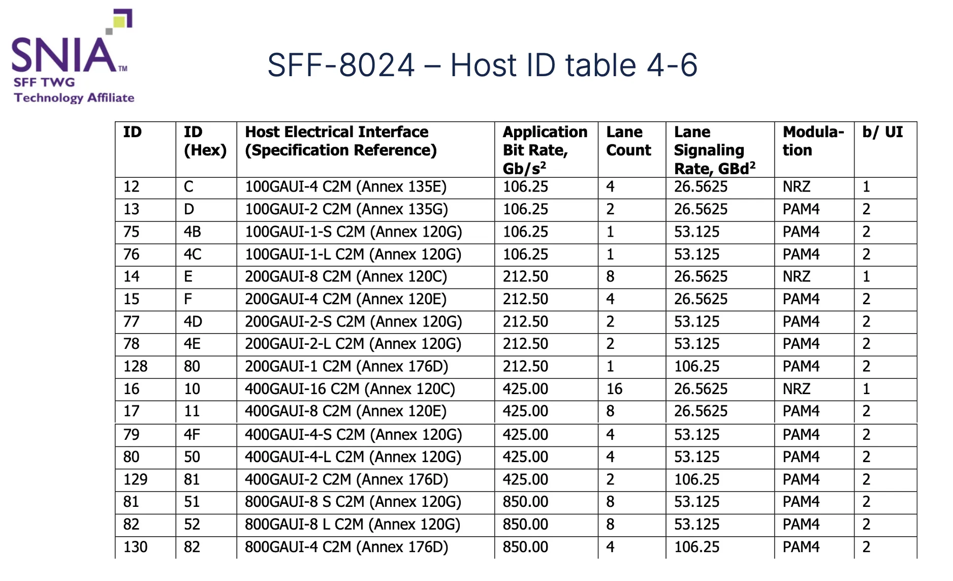
Modern coherent optics installed in a router are Ethernet based on the host
side and follow IEEE standards. Pluggable DCO are found in muxponders, with
the host side of the muxponder following FOIC (FlexO Interface) standards
based on OTN mapping.
Optics configuration using CMIS Applications
What is an “Application”
The following definition from the CMIS IA:
- An Application is a type of functional transmission configuration that is
characterized by specific signal propagation or signal processing between one
or more host lanes and one or more media lanes, overall providing a
well-defined signal or data transmission function to the host. - An Application instance is one implementation of an Application by a module
- An Application is typically characterized and specified by reference to a
pair of industry standards, one for the host interface and one for the media
interface, each comprising one or more lanes. These interface standards define
all necessary attributes for the respective interface, including the signaling
rate (Baud rate), the signaling modulation format, the number of lanes, as
well as any digital processing (such as lane alignment or FEC encoding and
decoding) of the data stream (if applicable).
Application Descriptor
The Application Descriptor includes the information required to configure a
specific application. This inclues the Host Interface ID, Media Interface ID, the
number of lanes for each interface, and then assignment options for each lane. In
the context of pluggable coherent optics in a router, the media lane count will
be one since there is a single output wavelength. CMIS is flexible enough to allow
per-lane Applications, but for pluggable DCO in a router, the same application is
used across all lanes.
Application Selection (AppSel) Code
Each Application Descriptor is identified by a unique AppSel code (short for
Application Selection code). The AppSel code is a pointer to a specific
Application Descriptor. When the network operating system configures an optic,
it uses the single AppSel Code. The AppSel codes are advertised by the optics as
a numeric list.
The AppSel codes are not standardized across the industry, meaning even if the
Media and Host Interface ID are using a standard value, the AppSel code could be
different across two different optics.
Expanded AppSel codes in CMIS 5.3+
The original AppSel code table in CMIS was limited to 15 unique AppSel codes. The
flexibility of DCO required expanding the available AppSel codes. CMIS 5.3 introduced
an extended AppSel code table now capable of 240 AppSel codes.
Application Attributes and Descriptions
CMIS has also added functionality to retrieve more information about the
AppSel code. One key information added is the estimated power level utilized
by an Application. This may allow a host to use a power-optimized Application.
Additional capability advertisement is extended through C-CMIS.
The basic list of AppSel codes is just a numeric list without human-readable
descriptions. CMIS has added storage and retrieval of Interface Code
Descriptions. This is referred to as the 0x51h request and reply codes. The following
highlights the information returned in the 0x51h response.
| Field Name | Description |
|---|---|
| InterfaceID | Unmodified CMD Data |
| InterfaceLocation | Unmodified CMD Data |
| InterfaceName | ASCII[16]: Short Name |
| InterfaceDescription | ASCII[48]: Description and Specification Reference |
| InterfaceDataRate | F16: Application Bit Rate in Gb/s |
| InterfaceLaneCount | U16: Number of parallel lanes |
| LaneSignalingRate | F16: Lane Signaling Rate in GBd |
| Modulation | ASCII[16]: Lane Modulation Format |
| BitsPerSymbol | U16: Bits per Lane Modulation Symbol (rounded) |
| BitsPerSymbolExact | F16: Bits per Lane Modulation Symbol (not rounded) |
| GridSpacingMin | F16: Smallest optical grid spacing in GHz |
Sample AppSel code table in IOS-XR
The following shows a trucated list of AppSel codes for a Cisco 800ZR+ DCO. The picture
shows three codes, but there are 128! AppSel codes in total supported.
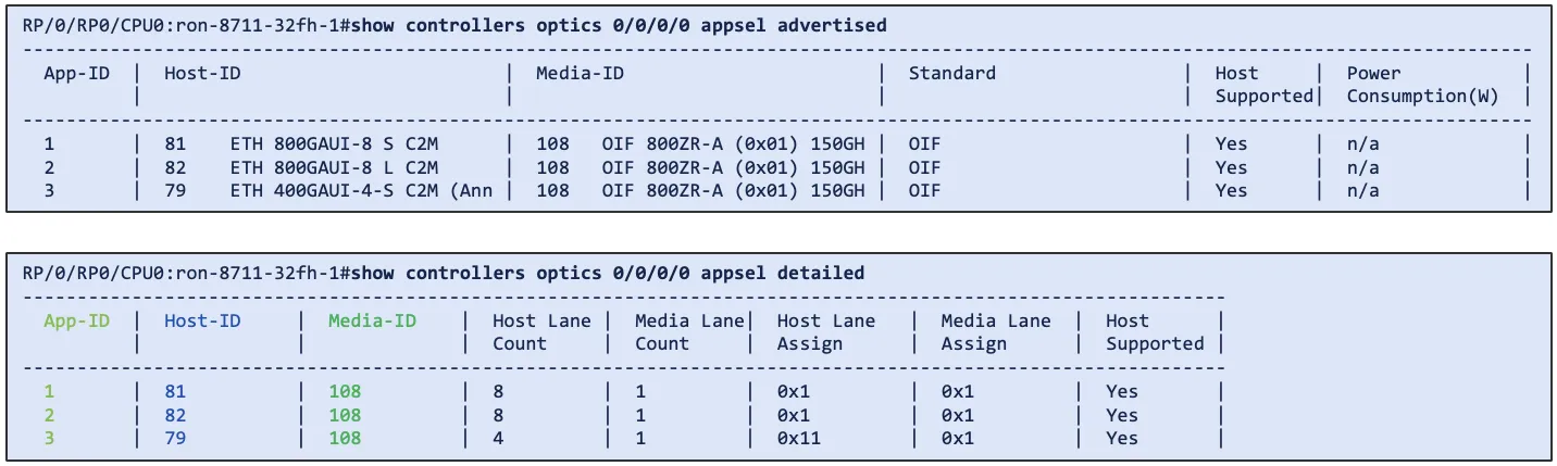
The translation of the Host ID and Media ID to a standard shown is done by IOS-XR. IOS-XR stores
a static table of SFF-8024 descriptions for standards-based Interface IDs. AppSel codes using
non-standard Interface ID descriptions and properties are retrieved using the CMIS 5.3+ 0x51h CDB request
method to dynamically populate the table.
AppSel code breakdown
The following picture highlights details around a single AppSel code.
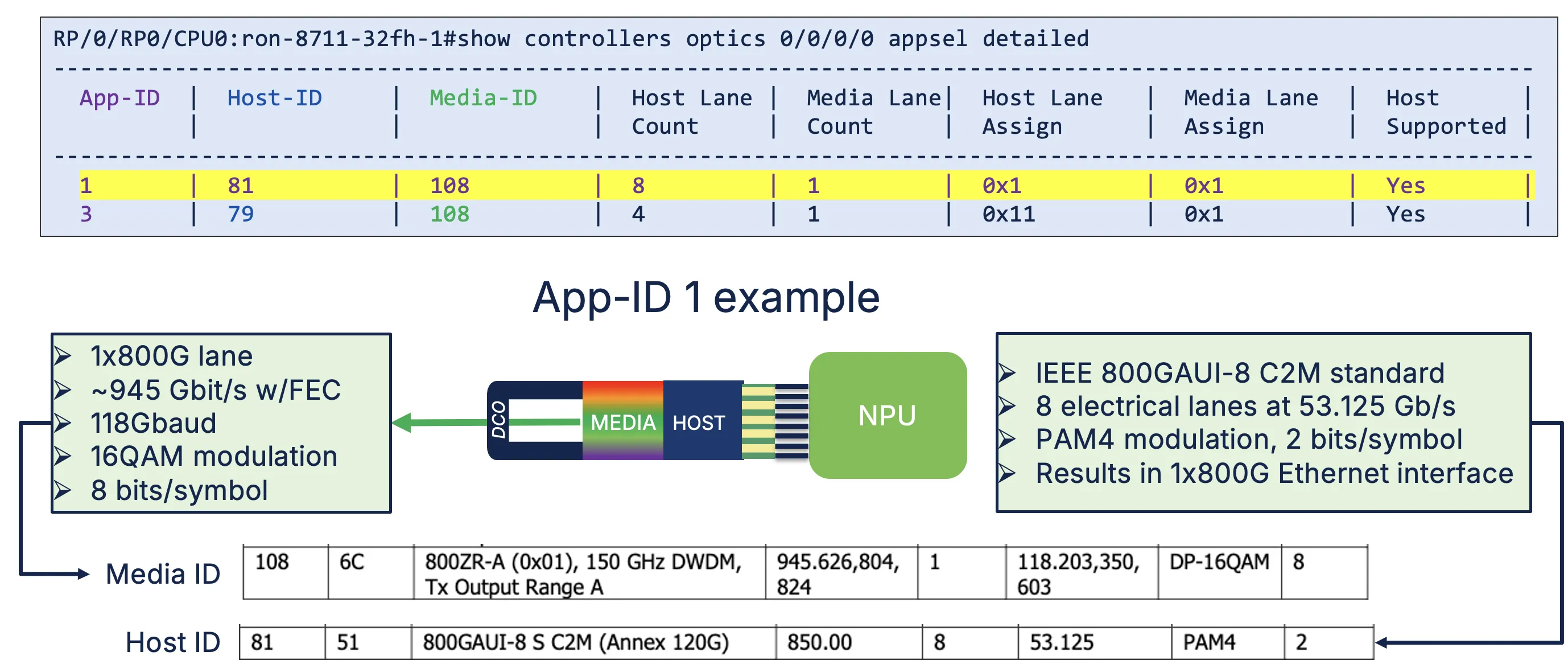
AppSel code 1 from this 800G-ZR+ transceiver has a Host Interface ID of 81 and a Media Interface ID of
108. These are both standardized and included within their respective SFF-8024 tables.
Media ID 108d in the SFF-8024 single mode fiber table has the following
properties:
Media ID 108 properties
- 800-ZRA standard
- 150Ghz spectral width
- 945.626 Gbps rate with overhead
- 1 lane
- 118.203 GBaud lane rate
- DP-16QAM modulation
- 8 bits/symbol
Host ID 81d in the SFF-8024 electrical host table has the following
properties:
Host ID 81 properties
- IEEE 800GAUI-8 standard
- 850 Gbit/s rate with overhead
- 945.626 Gbps rate with FEC overhead
- PAM4 modulation
- 53.125 Gbit/s lane rate
- 2 bits/symbol
IOS-XR CLI to configure AppSel code
The CLI in IOS-XR used to configure AppSel is straightforward. Once the user knows
the appropriate mode they want to use to configure the optics the following
command is used:
controller Optics0/0/0/0
 appsel simple code 1
The following command is used to view the current active AppSel
RP/0/RP0/CPU0:ron-8711-32fh-1#show controllers optics 0/0/0/0 appsel active
Mon Jun 22 10:34:24.659 PDT
 Instance:1
 App-ID:1
 Host-ID:81 ETH 800GAUI-8 S C2M
 Media-ID:108 OIF 800ZR-A (0x01) 150GHz DWDM TxO
 Host Lane Count:8
 Media Lane Count:1
 Host Lane Assign:0x1
 Media Lane Assign:0x1
Host configuration
The AppSel command configures the media and host side of the transceiver, but
it does NOT configure the host NPU. Previous optics such as the QDD-400G-ZRP-S
configured using the “breakout” command would configure both the optics as
well as the NPU.
Optics using AppSel configuration will continue to use the “breakout” or similar
hw-module command to configure the host NPU. As an example the AppSel code
If an incorrect combination of AppSel and host configuration is applied the host
will generate a system alarm.
P/0/RP0/CPU0:ron-8711-32fh-1#show alarms brief system active | inc Application
Mon Jun 22 10:39:38.562 PDT
0/RP0/CPU0 Major Software 06/22/2026 10:35:52 PDT Optics0/0/0/0 - hw_optics: Optics Application code select using simple mode with host and media ID failed
As an example, AppSel code 3 on the 800G-ZR+ utilized 1x800G on the media side
and 2x400G on the host side.
3 | 79 ETH 400GAUI-4-S C2M (Ann | 108 OIF 800ZR-A (0x01) 150GH | OIF
On the 8711-32FH example platform we are using this requires the following configuration.
hw-module port-range 0 1 instance 0 location 0/RP0/CPU0 mode 2x400
AppSel usage in Routed Optical Networking automation
Crosswork Hierarchical Controller
Starting in the RON 4.0 release, the automation tools such as Crosswork
Hierarchical Controller and the NSO RON Function Pack utilize AppSel selection
to configure all optics. The use of AppSel provides a single unified way to configure
all optics. If the optics do not support AppSel in the XR CLI, the AppSel configuration
is translated to legacy CLI.
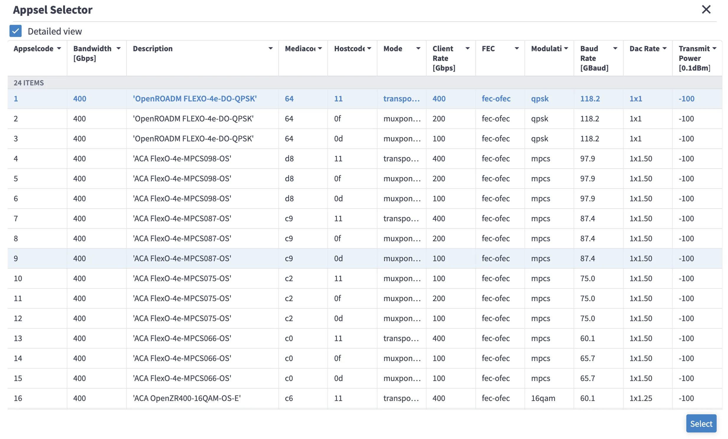
Cisco NSO Routed Optical Networking Function Pack
Starting with the RON 4.0 NSO RON function pack the input to provision optics is
now a single AppSel code value. The settings for speed, modulation, and DAC-Rate
have been deprecated.
Additional Resources
Routed Optical Networking Design Guide
Routed Optical Networking Landing Page
https://www.cisco.com/site/us/en/solutions/routed-optical-networking/index.html