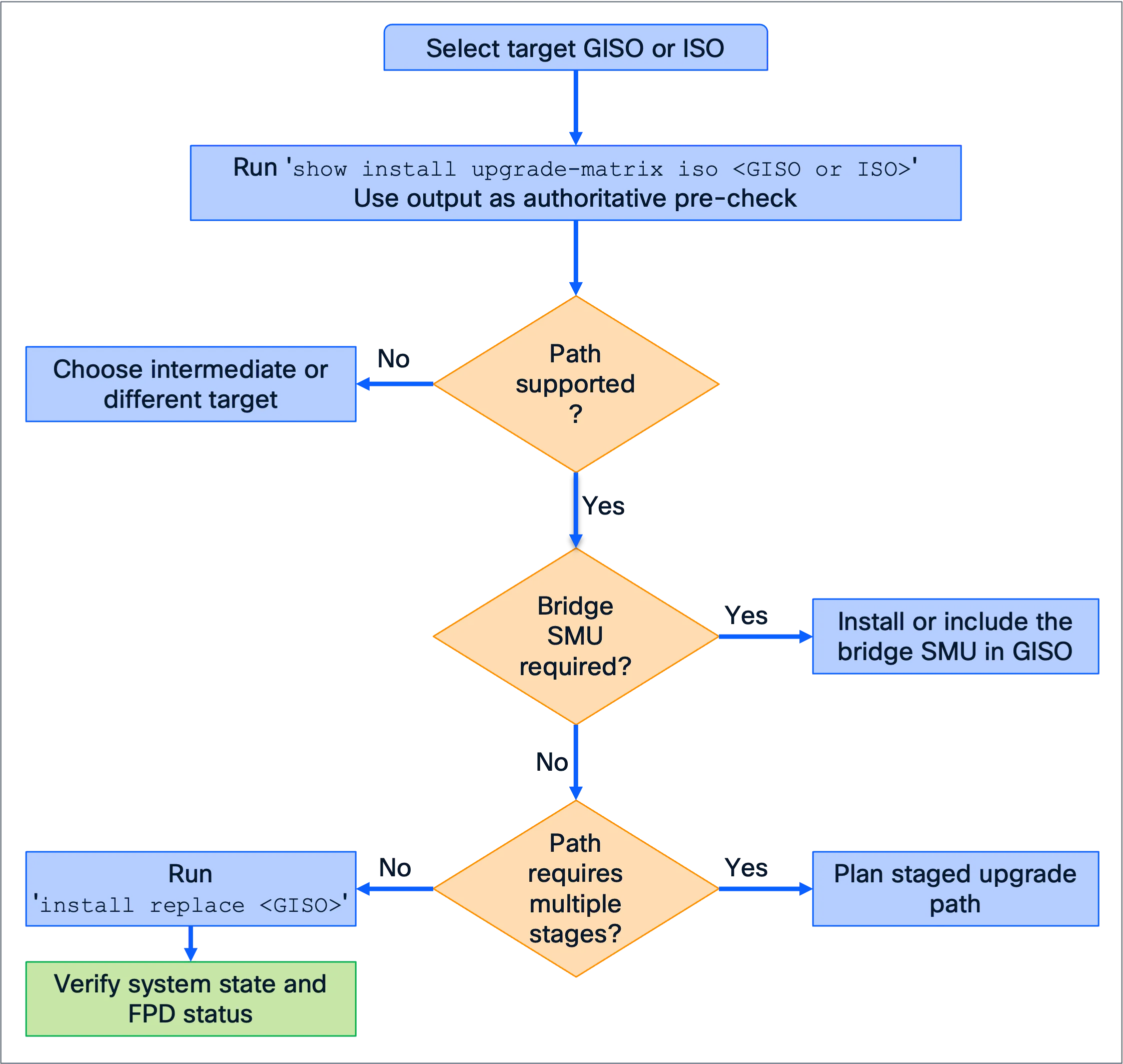
RSVP-TE Preemption on Cisco 8000
Preemption Overview
Resource Reservation Protocol with Traffic Engineering extensions (RSVP-TE) preemption allows a higher-priority Label Switched Path (LSP) to obtain bandwidth by displacing lower-priority reservations when resources are constrained. Hard preemption releases the displaced LSP immediately and can interrupt traffic. Soft preemption keeps forwarding active temporarily while the ingress Label Edge Router (LER) establishes a replacement path, reducing traffic disruption.
Multiprotocol Label Switching (MPLS) traffic engineering (TE) tunnel priority values range from 0 (highest) to 7 (lowest). The setup and holding priorities assigned to each LSP determine how that LSP participates in preemption. A higher-priority LSP can displace an established lower-priority LSP to reclaim bandwidth when the link’s available bandwidth is not sufficient.
| Term | Purpose |
|---|---|
| Setup priority | Determines whether an LSP can preempt existing LSPs during establishment. |
| Holding priority | Determines how strongly an established LSP resists being preempted. |
| Hard preemption | Immediately tears down the displaced LSP and releases its reservation. |
| Soft preemption | Allows forwarding to continue temporarily while a replacement LSP is established. |
In IOS XR MPLS-TE, each TE tunnel has a setup priority and a holding priority. When a higher-priority LSP cannot obtain sufficient bandwidth, it can preempt an established lower-priority LSP to obtain the required resources. On Cisco 8000, the preemption algorithm is optimized when building the preemption list. The algorithm behavior depends on the size of the bandwidth deficit, with the objective of minimizing both the number of LSPs and the amount of bandwidth that must be preempted.
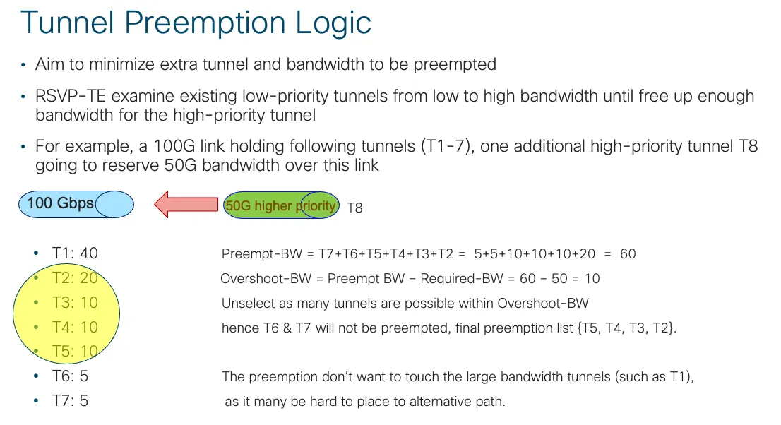
Figure 1: Tunnel preemption logic and overshoot refinement.
The default RSVP-TE preemption behavior is hard preemption. It is appropriate when resources must be reclaimed immediately because of actual resource contention. Soft preemption is useful for network maintenance—for example, when LSPs must be moved away from an interface before the interface is taken out of service without unnecessarily interrupting traffic. Soft preemption is also useful in dynamic traffic environments where RSVP-TE tunnel auto-bandwidth is deployed and preemption may occur more frequently.
Hard preemption is the traditional behavior. The lower-priority LSP is torn down immediately, and the ingress LER is notified through RSVP signaling. The headend can attempt to establish a replacement LSP on an eligible alternative path. The displaced LSP releases its bandwidth reservation. Because the old data path can disappear before the replacement path is ready, packets may be lost during the transition.
Soft preemption, standardized in RFC 5712, was introduced to reduce traffic disruption. Instead of immediately tearing down the preempted LSP, the network signals the ingress LER that the LSP needs to be rerouted while allowing forwarding to continue temporarily for a configurable period. The ingress LER can then establish a replacement path using a make-before-break approach. Once the replacement LSP is established, the old LSP reservation can be released. Even though the old LSP’s forwarding state is retained temporarily, the local bandwidth accounting is released immediately. Network congestion or expiry of the soft-preemption timer can still cause traffic disruption.
Preemption Lab Exercises
The lab uses a Cisco 8223 router (8223-64EF-M), based on the P200 ASIC and running IOS XR 26.2.1. All router core-facing links are bundle interfaces, and the RSVP bandwidth pool is configured to the full link capacity. RSVP-TE tunnel LSPs are established with an initial signaled bandwidth as the baseline. RSVP-TE tunnel auto-bandwidth is enabled, and events are triggered by router reconfiguration or link-status changes.
Consider a typical customer network in which MPLS-TE provides classified traffic over the intended tunnel LSP data paths. When sufficient bandwidth is available to satisfy all tunnel reservations, the shortest path is preferred. In the lab topology, all tunnels sourced on Provider Edge (PE) router PE1 initially use the shortest path over the direct link to PE2. If the direct connection does not have sufficient bandwidth, some tunnels must use a longer path through the core router to reach PE2. PE1 and PE2 are the provider edge routers, P1 is the provider (P) core router, and CE1 and CE2 are customer edge (CE) routers. The orange path uses the direct BE200 link; the green path uses BE400 and BE500 through P1.
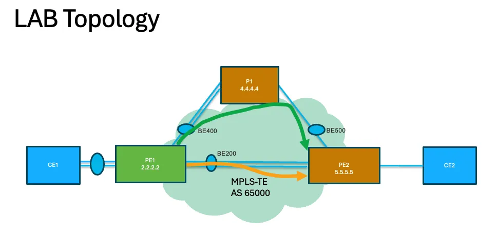
Figure 2: Lab topology with the direct BE200 path and alternate BE400/BE500 path.
RSVP-TE preemption can be triggered in two common scenarios:
- Arrival of a new bandwidth reservation with a higher priority than existing reservations.
- Reduction in available link bandwidth—for example, because of RSVP bandwidth-pool configuration changes or dynamic events such as bundle-interface member-link flaps.
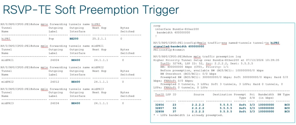
In the soft-preemption example, tunnel hiPRI is configured with setup/holding priorities of 1/1, while tunnels midPRI1, midPRI2, and midPRI3 use setup/holding priorities of 3/3 with soft preemption enabled. Initially, all PE1 tunnels take the shortest path over bundle BE200 toward PE2.
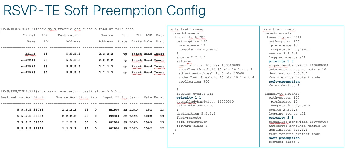
Figure 3: Initial tunnel reservations and the shown soft-preemption configuration.
Initial tunnel state
RP/0/RP0/CPU0:PE1#show mpls traffic-eng tunnels tabular role head
 Tunnel LSP Destination Source Tun FRR LSP Path
 Name ID Address Address State State Role Prot
------------------------------------------------------------
 hiPRI 51 5.5.5.5 2.2.2.2 up Inact Head Inact
midPRI1 23 5.5.5.5 2.2.2.2 up Inact Head Inact
midPRI2 33 5.5.5.5 2.2.2.2 up Inact Head Inact
midPRI3 37 5.5.5.5 2.2.2.2 up Inact Head Inact
Initial RSVP reservations
RP/0/RP0/CPU0:PE1#show rsvp reservation destination 5.5.5.5
Destination Add DPort Source Add SPort Pro Input IF Sty Serv Rate Burst
--------------- ----- ---------- ----- --- -------- --- ---- ---- -----
 5.5.5.5 32768 2.2.2.2 51 0 BE200 SE LOAD 15G 1K
 5.5.5.5 32856 2.2.2.2 23 0 BE200 SE LOAD 100G 1K
 5.5.5.5 32857 2.2.2.2 33 0 BE200 SE LOAD 100G 1K
 5.5.5.5 32858 2.2.2.2 37 0 BE200 SE LOAD 100G 1K
hiPRI configuration
mpls traffic-eng
 named-tunnels
 tunnel-te hiPRI
 path-option 100
 preference 10
 computation dynamic
!
 source 2.2.2.2
 auto-bw
 bw-limit min 100 max 400000000
 overflow threshold 30 min 10 limit 2
 adjustment-threshold 3 min 25000
 underflow threshold 10 min 10 limit 4
 application 900
!
!
 logging events all
 priority 1 1
 signalled-bandwidth 15000000
 autoroute announce
!
 destination 5.5.5.5
 fast-reroute
 soft-preemption
 forward-class 6
!
midPRI1 and midPRI2 configuration
mpls traffic-eng
 named-tunnels
 tunnel-te midPRI1
 path-option 100
 preference 10
 computation dynamic
 source 2.2.2.2
 logging events all
 priority 3 3
 signalled-bandwidth 100000000
 autoroute announce metric 10
 destination 5.5.5.5
 fast-reroute protect node
 soft-preemption
 forward-class 1
!
 tunnel-te midPRI2
 path-option 100
 preference 10
 computation dynamic
!
 source 2.2.2.2
 logging events all
 priority 3 3
 signalled-bandwidth 100000000
 autoroute announce metric 10
 destination 5.5.5.5
 fast-reroute protect node
 soft-preemption
 forward-class 2
When the high-priority hiPRI tunnel increases its bandwidth reservation and the request cannot be admitted with the available bandwidth, RSVP must preempt lower-priority local reservations. In this example, hiPRI increases its reservation to 400G, exhausting the available bandwidth on the BE200 shortest-path link. The lower-priority tunnels midPRI1, midPRI2, and midPRI3 are soft-preempted. The ingress LER reroutes them over the longer alternative path (bundle BE400) via P1 using make-before-break, allowing forwarding to continue during the transition.
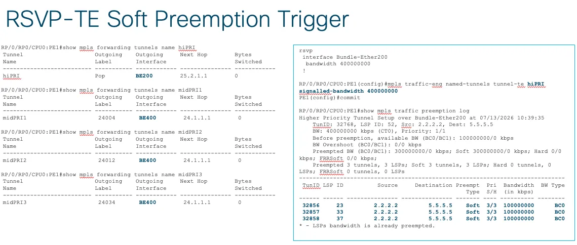
Figure 4: Manual reservation increase, selected victims and forwarding interfaces.
Reservable pool and manual trigger
rsvp
 interface Bundle-Ether200
 bandwidth 400000000
!
RP/0/RP0/CPU0:PE1(config)#mpls traffic-eng named-tunnels tunnel-te hiPRI
signalled-bandwidth 400000000
PE1(config)#commit
Preemption log
RP/0/RP0/CPU0:PE1#show mpls traffic preemption log
Higher Priority Tunnel Setup over Bundle-Ether200 at 07/13/2026 10:39:35
 TunID: 32768, LSP ID: 52, Src: 2.2.2.2, Dest: 5.5.5.5
 BW: 400000000 kbps (CT0), Priority: 1/1
 Before preemption, available BW (BC0/BC1): 100000000/0 kbps
 BW Overshoot (BC0/BC1): 0/0 kbps
 Preempted BW (BC0/BC1): 300000000/0 kbps;
 Soft 300000000/0 kbps; Hard 0/0 kbps; FRRSoft 0/0 kbps;
 Preempted 3 tunnels, 3 LSPs;
 Soft 3 tunnels, 3 LSPs; Hard 0 tunnels, 0 LSPs;
 FRRSoft 0 tunnels, 0 LSPs
 TunID LSP ID Source Destination Preempt Pri Bandwidth BW Type
 Type S/H (in kbps)
------------------------------------------------------------------
 32856 23 2.2.2.2 5.5.5.5 Soft 3/3 100000000 BC0
 32857 33 2.2.2.2 5.5.5.5 Soft 3/3 100000000 BC0
 32858 37 2.2.2.2 5.5.5.5 Soft 3/3 100000000 BC0
 * - LSPs bandwidth is already preempted.
Forwarding interfaces after preemption
RP/0/RP0/CPU0:PE1#show mpls forwarding tunnels name hiPRI
Tunnel Outgoing Outgoing Next Hop Bytes
Name Label Interface Switched
------------------------- -------- ----------- ---------- ----------
hiPRI Pop BE200 25.2.1.1 0
RP/0/RP0/CPU0:PE1#show mpls forwarding tunnels name midPRI1
Tunnel Outgoing Outgoing Next Hop Bytes
Name Label Interface Switched
------------------------- -------- ----------- ---------- ----------
midPRI1 24004 BE400 24.1.1.1 0
RP/0/RP0/CPU0:PE1#show mpls forwarding tunnels name midPRI2
Tunnel Outgoing Outgoing Next Hop Bytes
Name Label Interface Switched
------------------------- -------- ----------- ---------- ----------
midPRI2 24012 BE400 24.1.1.1 0
RP/0/RP0/CPU0:PE1#show mpls forwarding tunnels name midPRI3
Tunnel Outgoing Outgoing Next Hop Bytes
Name Label Interface Switched
------------------------- -------- ----------- ---------- ----------
midPRI3 24034 BE400 24.1.1.1 0
Preemption priorities are assigned and signaled through RSVP-TE signaling. The requesting LSP’s setup priority is compared with the established LSP’s holding priority. RSVP-TE carries the setup and holding priorities in the SESSION_ATTRIBUTE object of PATH messages, as defined in RFC 3209. To support preemption-history tracking, link management records bandwidth released through preemption. In this soft-preemption lab example, RSVP tracks the bandwidth and number of LSPs that were soft-preempted and rerouted from the local link to the alternative path.
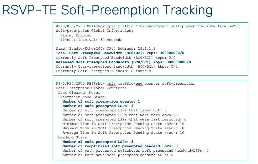
Figure 5: Corrected illustrative example of soft-preemption accounting and counters.
The tracking output is a corrected illustrative example based on the original lab material. The timeout counter was corrected; this figure does not represent a new test run.
Soft-preemption link accounting
RP/0/RP0/CPU0:PE1#show mpls traffic link-management soft-preemption interface be200
Soft-preemption Global Information:
 State: Enabled
 Timeout Interval: 30 seconds
Name: Bundle-Ether200; IPv4 Address: 25.1.1.2
Total Soft Preempted Bandwidth (BC0/BC1) kbps: 300000000/0
Currently Soft Preempted Bandwidth (BC0/BC1) kbps: 0/0
Released Soft Preempted Bandwidth (BC0/BC1) kbps: 300000000/0
Currently Over-subscribed Bandwidth (BC0/BC1) kbps: 0/0
Currently Soft Preempted Tunnels: 0 tunnels
Soft-preemption counters
RP/0/RP0/CPU0:PE1#show mpls traffic-eng counter soft-preemption
Soft-preemption Global Counters:
 Last Cleared: Never
 Preemption Node Stats:
 Number of soft preemption events: 1
 Number of soft preempted LSPs: 3
 Number of soft preempted LSPs that timed out: 0
 Number of soft preempted LSPs that were torn down: 0
 Number of soft preempted LSPs that were fast rerouted: 0
 Minimum Time in Soft Preemption Pending State (sec): 10
 Maximum Time in Soft Preemption Pending State (sec): 10
 Average Time in Soft Preemption Pending State (sec): 10
 Headend Stats:
 Number of soft preempted LSPs: 3
 Number of reoptimized soft preempted headend-LSPs: 3
 Number of path protected switchover soft preempted headend-LSPs: 0
 Number of torn down soft preempted headend-LSPs: 0
Preemption can also be triggered when the MPLS link bandwidth pool is reduced, either by manually configuring a smaller bandwidth pool or because of bundle-interface member-link flaps. In both cases, the reduction in available bandwidth can make existing reservations infeasible, causing lower-priority tunnels to be preempted and, when soft preemption is enabled, rerouted gracefully.
Cisco 8000 optimizes the RSVP-TE preemption algorithm to minimize traffic disruption and the number of LSPs that must be preempted. When a core-network bundle-interface bandwidth reduction, such as a member-link flap, creates a deficit, the router calculates the deficit from the total LSP-reserved bandwidth minus the link’s new maximum reservable bandwidth. In the following illustrated lab examples, both cases build the initial preemption list in ascending bandwidth order of low-priority LSPs and then prune the list if an overshoot occurs. In the large-deficit example, the final selection contains the larger tunnels. The final lists in these examples are as follows:
- Smaller bandwidth deficit: the final preemption list contains the two 50 Gbps LSPs.
- Larger bandwidth deficit: the final preemption list contains the 300 and 500 Gbps LSPs.
The first lab scenario covers MPLS link bandwidth-pool reconfiguration. The router computes the bandwidth deficit after the pool is reduced and begins the preemption process. The deficit is calculated as the total LSP-reserved bandwidth on the link minus the link’s new maximum reservable bandwidth after the adjustment. The router then identifies lower-priority LSPs that need to be preempted. For a small deficit, the algorithm favors lower-bandwidth tunnels when building the preemption list.
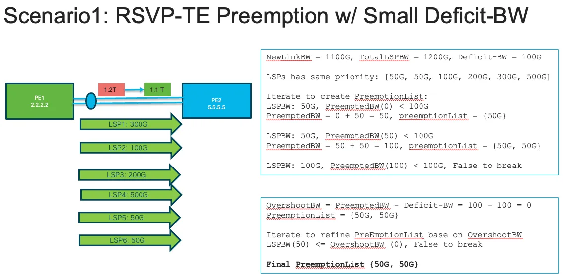
Figure 6: A 100 Gbps deficit after the reservable pool decreases from 1.2 Tbps to 1.1 Tbps.
If the initial preemption list captures more bandwidth than required, the algorithm refines the list. When the selected lower-priority tunnels overshoot the actual deficit, lower-bandwidth LSPs whose reserved bandwidth is less than or equal to the overshoot amount are removed from the preemption list. In the illustrated same-priority examples, candidate LSPs are accumulated in ascending bandwidth order until the deficit is covered. During the second refinement pass, candidate LSPs that fit within the current overshoot are removed, and the overshoot is updated after each removal.
The second lab scenario covers an MPLS bundle-interface member-link flap, which significantly reduces the bundle-interface bandwidth pool. The router computes the bandwidth deficit and starts soft preemption after the MPLS bundle bandwidth pool reaches its limit. In the example, an overshoot remains after the first-round preemption list is built. The preemption process refines the list by removing lower-bandwidth LSPs when their reserved bandwidth is less than or equal to the overshoot amount.
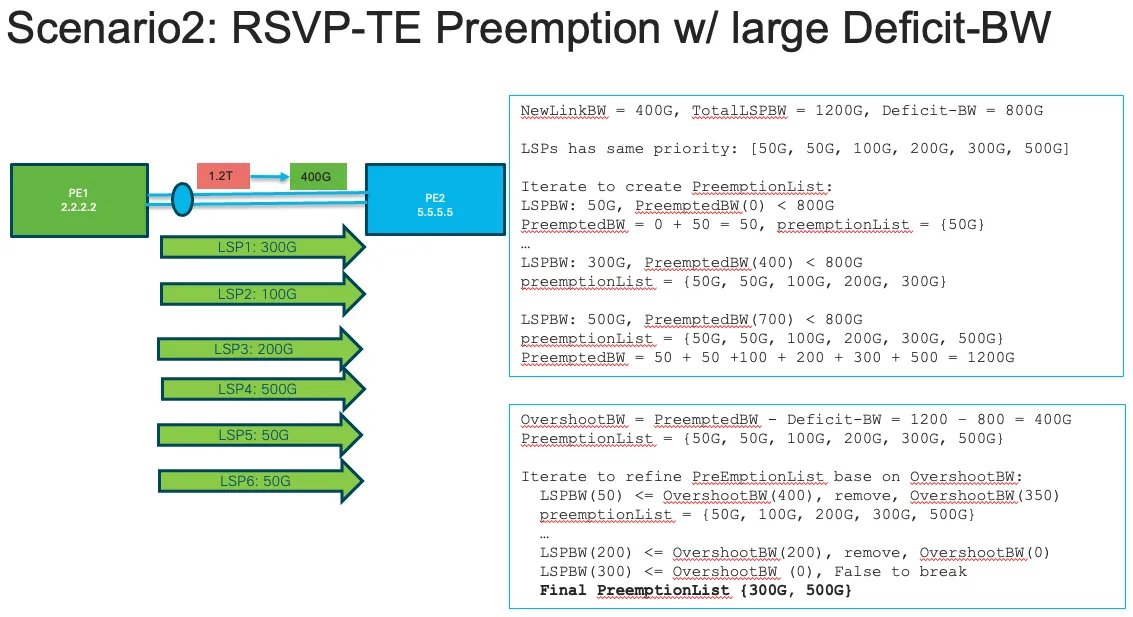
Figure 7: An 800 Gbps deficit after the reservable pool decreases from 1.2 Tbps to 400 Gbps.
In summary, IOS XR RSVP-TE preemption allows higher-priority LSPs to be admitted when the link bandwidth pool is constrained by preempting lower-priority reservations. Hard preemption releases resources immediately but can cause traffic disruption, while soft preemption allows affected LSPs to be rerouted gracefully using make-before-break. In case of MPLS link bandwidth pool reduction, preemption-list selection is optimized based on the size of the bandwidth deficit relative to existing lower-priority LSP reservations.
References
1. XRDocs TE++ Auto-Capacity tutorial
Configuration and operational examples for auto-bandwidth and LSP splitting and merging on Cisco 8000.
2. XRDocs Cisco 8000 PBTS Implementation Basic
Traffic classification and forward-class selection examples for steering traffic into MPLS-TE tunnels.
3. RFC 3209 — RSVP-TE Extensions to RSVP for LSP Tunnels
Sections 2.5, 3.1, 4.6.4 and 4.7 cover make-before-break, PATH signaling, bandwidth changes and SESSION_ATTRIBUTE priorities.
4. RFC 5712 — MPLS Traffic Engineering Soft Preemption
Sections 4, 6 and 7 describe soft-preemption signaling, local bandwidth accounting and timeout behavior.
5. RFC 3181 — Signaled Preemption Priority Policy Element
Related background on RSVP policy-priority encoding. This policy element is distinct from the RSVP-TE setup and holding priorities defined in RFC 3209.