Multicast Services over SRv6 / IPv6 Cores
Introduction
Service provider cores are steadily moving toward IPv6-only transport and Segment Routing over IPv6 (SRv6) services, but multicast cannot be treated as an afterthought. The goal is to carry existing multicast VPN use cases forward without introducing a separate multicast transport model or SRv6-specific replication behavior.
The approach described here keeps the provider multicast tree native to IPv6 and uses BGP Multicast VPN (MVPN) for service signaling. SRv6 remains the unicast and service context; multicast forwarding is handled by PIMv6-SSM and IP-in-IP encapsulation.
This article is structured in three parts. The first covers Multicast VPN fundamentals: core tree types, Multicast Distribution Tree (MDT) mechanisms, and PMSI concepts that apply to any MVPN deployment regardless of transport. The second presents Cisco’s multicast architecture for SRv6 / IPv6 cores, showing how these fundamentals are realized using native IPv6 multicast, PIMv6-SSM, and BGP MVPN over an IPv6 core used for SRv6 services. The third provides sample configuration and verification tied to a reference topology, so the reader can move from concept to deployment.
Why Multicast Matters
Multicast workloads continue to grow across service provider, enterprise, and government networks, driven by live media, IPTV, financial market data, surveillance, and IoT. As these networks migrate to SRv6, multicast services must migrate with them.
The architecture described in this article ensures multicast carries forward into IPv6/SRv6 networks natively, without parallel infrastructure or protocol overlays outside the IPv6 stack.
Multicast VPN Fundamentals
Before examining the IPv6-native solution, it is essential to understand the foundational Multicast VPN concepts that underpin the architecture. This section covers the building blocks, core tree types, and MDT mechanisms that any multicast VPN deployment relies on, regardless of the underlying transport.
Core Trees
In an MVPN architecture, provider edge (PE) routers must deliver customer multicast traffic across the provider core without requiring core routers to hold per-VPN state. This is achieved through core trees: provider-level multicast distribution trees that carry encapsulated customer traffic between PEs.
The core tree is formally referred to as a Provider Multicast Service Interface (PMSI). The PMSI abstracts the provider core as a multicast-capable tunnel connecting PEs participating in a given VPN.
Point-to-Multipoint Trees
A point-to-multipoint (P2MP) tree has a single root, the ingress PE, and multiple leaves, the egress PEs with interested receivers. Unlike point-to-point tunnels that require a separate path per destination, a P2MP tree replicates traffic at branching points in the core, delivering one copy of each packet to all interested receivers efficiently.
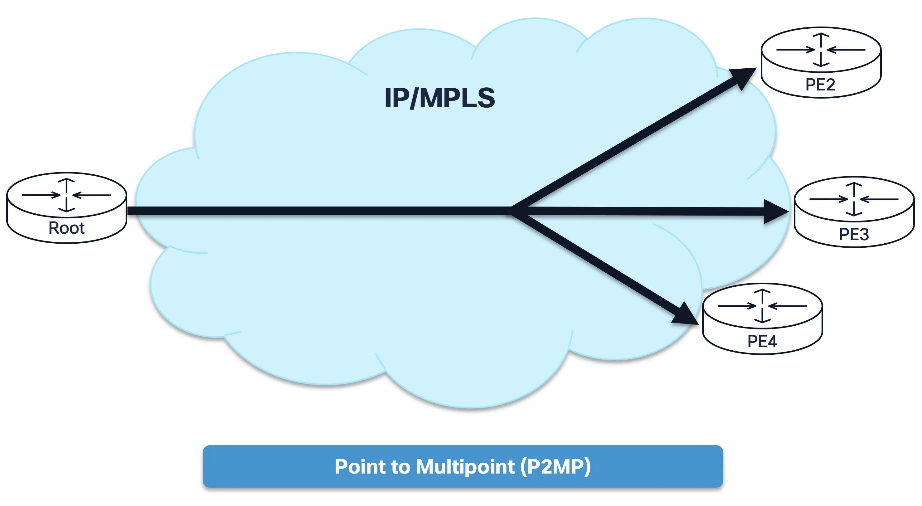
Figure 1: Point-to-multipoint (P2MP) tree with one ingress PE branching to multiple egress PEs. Core routers replicate traffic at branch points.
- The ingress PE acts as the root of the tree and sources customer multicast traffic into the core.
- Each egress PE with active receivers joins the tree as a leaf.
- Core P routers replicate traffic at branching points. They forward multicast without any awareness of the customer overlay.
- Tree construction is typically hop-by-hop using PIM joins toward the root PE’s address.
This model keeps provider core state proportional to the number of active multicast sources, not the number of customer flows.
PMSI Types
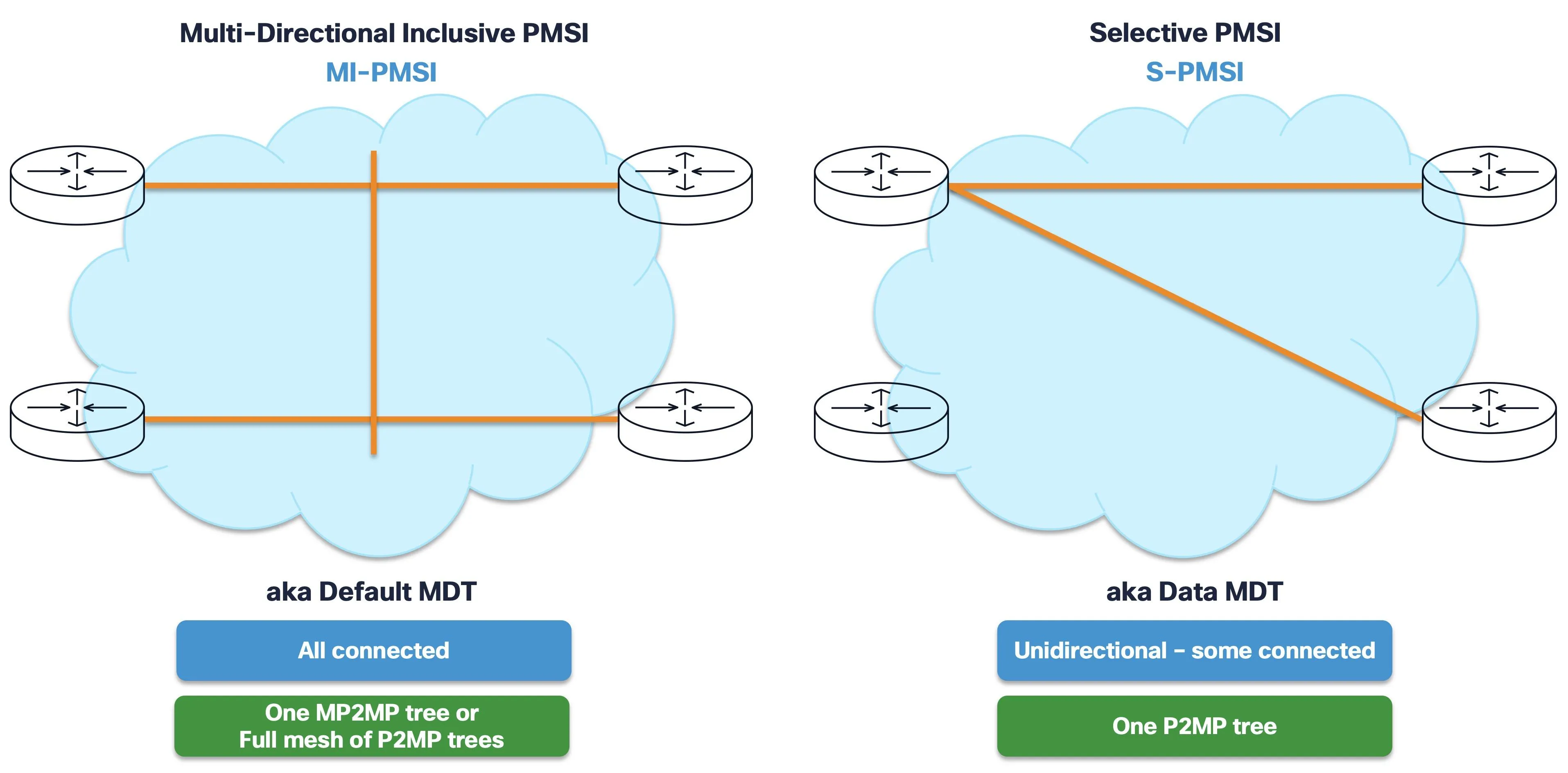
Figure 2: The two primary PMSI categories: I-PMSI, also known as Default MDT, connects all PEs, while S-PMSI, also known as Data MDT, connects only interested PEs.
The MVPN framework defines several PMSI types. The two most relevant are:
| PMSI type | Tree scope | Used for |
|---|---|---|
| Inclusive PMSI (I-PMSI) | Connects all PEs in a VRF | Default MDT |
| Selective PMSI (S-PMSI) | Connects only PEs with active receivers | Data MDT |
The I-PMSI is always present and carries control signaling and low-rate multicast traffic. The S-PMSI is created on demand to optimize high-rate flows by delivering them only to PEs that need them.
Default MDT
The Default MDT is the foundational tree that connects all PE routers participating in a multicast-enabled VPN Routing and Forwarding (VRF) instance. It is always active and serves as the baseline transport for customer multicast traffic and, in PIM-signaled models, customer multicast control messages.
When a VRF is configured with multicast, each PE is assigned a multicast group address for the Default MDT. All PEs in that VRF join this group, forming a shared multicast tree across the provider core.
From the perspective of PIM running in the customer VRF overlay, the Default MDT can act like a virtual LAN where all PEs appear as directly connected PIM neighbors. In the BGP C-multicast model validated in this article, PE discovery and customer multicast joins are signaled with BGP MVPN; the MDT provides the provider tunnel used to carry encapsulated customer multicast traffic.
Key characteristics:
- Always on – The Default MDT is established as soon as the VRF is configured with multicast, regardless of whether customer traffic is flowing.
- Carries baseline customer traffic – Customer multicast
(S,G)flows are initially forwarded on the Default MDT unless a Data MDT is triggered. - Separates overlay signaling from transport – In this BGP-signaled example, PE discovery and C-multicast joins are BGP MVPN routes, while the MDT is the provider transport tree.
- Shared across address families – A single Default MDT group serves both IPv4 and IPv6 customer multicast within the same VRF.
- One per VRF – Each multicast-enabled VRF has its own Default MDT with a unique multicast group.
Because all PEs in a VRF share a single Default MDT, the provider core maintains one multicast tree per VRF, not one per customer flow. This keeps core state manageable even as the number of customer (S,G) entries grows.
However, the Default MDT delivers traffic to all PEs in the VRF, including those without active receivers. For low-rate flows and control traffic, this overhead is acceptable. For high-bandwidth flows, the Data MDT provides a more efficient alternative.
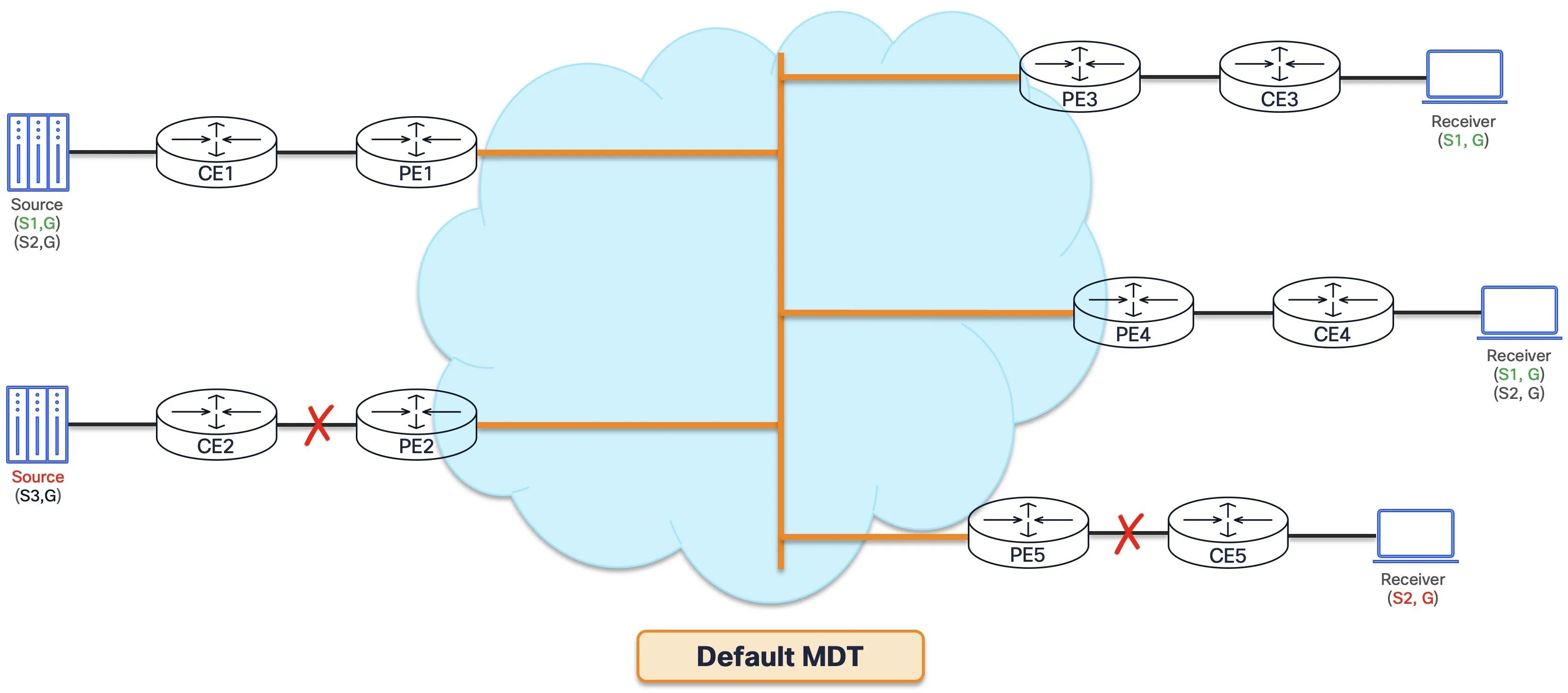
Figure 3: Default MDT delivers multicast traffic to all PEs in the VRF. PEs without interested receivers for a given flow drop the unwanted traffic.
Data MDT
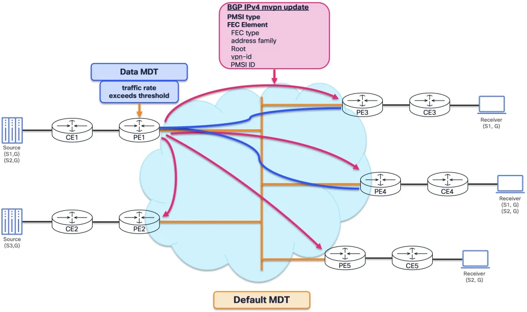
The Data MDT addresses the efficiency limitation of the Default MDT. While the Default MDT delivers traffic to all PEs in a VRF, the Data MDT creates a selective tree that only includes PEs with active receivers for a specific customer (S,G) flow.
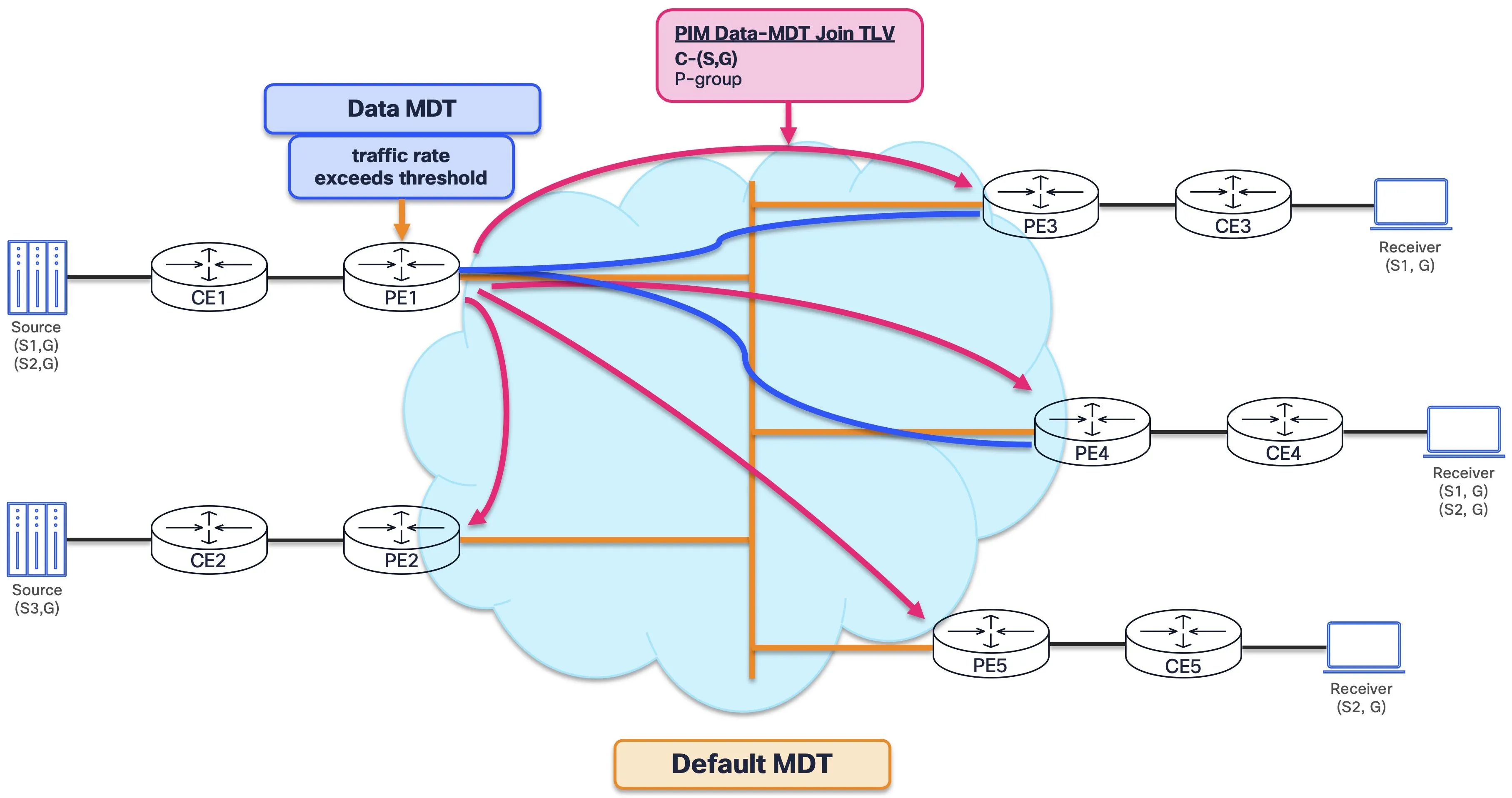
Figure 4: Data MDT creates a selective P2MP tree. Only PEs with active receivers join the Data MDT; PEs without receivers cache the signaling but do not join.
The sequence is:
| Step | Function |
|---|---|
| 1. Threshold trigger | The ingress PE monitors the traffic rate for each customer (S,G) on the Default MDT. When a flow exceeds a configurable bandwidth threshold, or immediately if configured, the ingress PE initiates a Data MDT. |
| 2. Signaling | The ingress PE advertises a BGP MVPN Type 3, S-PMSI Auto-Discovery, route to all PEs in the VRF. This route identifies the customer (S,G) and the new multicast group to be used for the Data MDT. |
| 3. Selective join | Only egress PEs with active receivers for that (S,G) join the new Data MDT tree in the core. PEs without receivers cache the advertisement but do not join. |
| 4. Switchover | After a brief hold-down period, the ingress PE moves the customer (S,G) traffic from the Default MDT onto the Data MDT. The flow is now delivered only to interested PEs. |
Key characteristics:
- Per-
(S,G)granularity – Each Data MDT carries a single customer(S,G)flow. Data MDTs apply to source-specific trees only, not shared trees. - On-demand creation – Data MDTs are created only when traffic exceeds the threshold, keeping core state minimal during low-traffic periods.
- Separate P2MP tree – Each Data MDT uses its own multicast group, creating an independent P2MP tree in the provider core.
- BGP-signaled – The Type 3 route ensures all PEs are informed of the switchover; egress PEs join autonomously based on receiver interest.
- Reversible – If the traffic rate drops below the threshold or receivers disconnect, the flow can move back to the Default MDT.
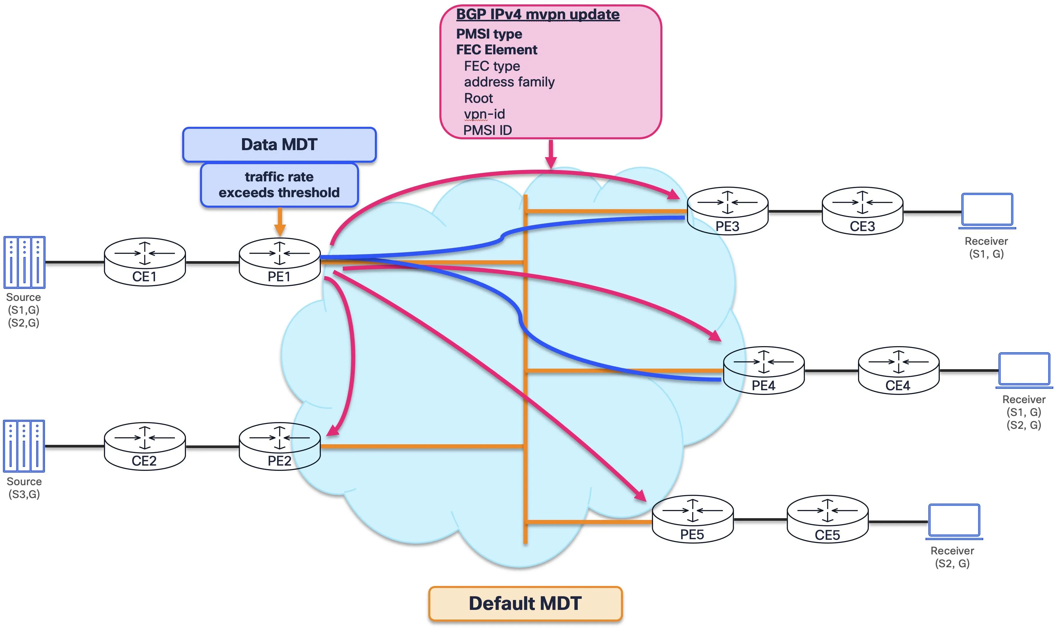
Figure 5: BGP IPv4 MVPN update carrying Data MDT information, including PMSI tunnel details used by the ingress PE to signal the Data MDT switchover.
| Aspect | Default MDT | Data MDT |
|---|---|---|
| Scope | All PEs in the VRF | Only PEs with active receivers |
| Activation | Always on | On demand, threshold-based |
| Traffic type | Control and low-rate data | High-rate (S,G) flows |
| Core tree | One per VRF | One per (S,G) flow |
| Signaling | BGP MVPN Type 1, Auto-Discovery | BGP MVPN Type 3, S-PMSI A-D |
In a typical deployment, the Default MDT handles baseline multicast connectivity and low-bandwidth multicast flows, while high-bandwidth streams such as IPTV channels and live video feeds are offloaded to Data MDTs for efficient delivery.
BGP Auto-Discovery and Signaling
Traditional MVPN, or Draft-Rosen, relied on PIM in the provider core for both tree construction and PE discovery. NG-MVPN, defined by RFC 6513 and RFC 6514, replaces this with BGP-based Auto-Discovery where PEs advertise their participation in a multicast VPN through BGP, eliminating the need for PIM adjacencies across the Default MDT for PE discovery.
BGP MVPN introduces two key functions:
- Auto-Discovery – PEs automatically learn which other PEs are enabled for multicast in a given VPN. Each PE advertises its loopback address and VPN membership via BGP, removing the need for manual configuration or PIM-based discovery.
- Customer signaling in overlay – Customer C-multicast Join and Prune messages are signaled via BGP rather than PIM between PEs. This means customer multicast state is carried in BGP updates as C-multicast routes, not as PIM messages flooded across the Default MDT.
Every BGP MVPN update that binds a customer multicast flow to a provider tunnel carries a PMSI Tunnel Attribute. The PTA contains two critical pieces of information:
- Tunnel type – Identifies the core tree protocol, such as PIM-SSM, mLDP P2MP, RSVP-TE P2MP, or IR. This tells the receiving PE how to join the provider tree.
- Tunnel identifier – Uniquely identifies the specific tunnel instance, such as the multicast group address for PIM-SSM or the FEC element for mLDP. This tells the receiving PE which tree to join.
The PTA connects the BGP MVPN control plane to the underlying provider multicast infrastructure. It is the bridge between the overlay signaling and the underlay tree.
The BGP MVPN address family defines seven route types in RFC 6514. The ones most relevant to this article are:
- Type 1, Intra-AS I-PMSI A-D – Each PE advertises its membership in a multicast VPN, establishing the Default MDT.
- Type 3, S-PMSI A-D – The ingress PE signals a Data MDT, binding a customer
(S,G)flow to a selective provider tunnel. - Type 5, Source Active A-D – The source PE advertises that a customer multicast source is active; this is relevant when the customer VRF uses PIM-SM.
- Type 6, Shared Tree Join – An egress PE signals interest in a customer shared tree; this is relevant when the customer VRF uses PIM-SM.
- Type 7, Source Tree Join – An egress PE signals interest in a customer source tree; this is used for source-tree joins, including SSM flows.
Other MVPN route types are outside the single-AS Default MDT verification scope used in the configuration example.
SRv6 / IPv6 Core Architecture
Cisco’s multicast strategy for SRv6 / IPv6 core networks is MVPN over an IPv6 core used for SRv6 services, using native PIMv6-SSM in the underlay and IP-in-IP encapsulation for customer traffic. In this architecture, multicast forwarding does not use SRv6 SIDs, Segment Routing Headers, or SRv6 packet formats; the provider tree is native IPv6 multicast. This leverages mature IPv6 multicast standards without requiring SRv6-specific multicast extensions. Multicast services share the same IPv6 core used for unicast and no separate multicast infrastructure is needed.
In the validation lab, SRv6 is configured so the environment represents an SRv6 L3VPN service, but multicast transport itself uses IPv6/PIMv6, not SRv6 SID/SRH forwarding.
The architecture builds on RFC 6513/6514 MVPN procedures, RFC 6515 for IPv6 infrastructure addresses, RFC 8950 for advertising IPv4 NLRI with IPv6 next-hops, and RFC 7761 for PIM-SM and PIM-SSM behavior. The SRv6 service context is based on RFC 8402 and RFC 8986, while Flex-Algo path influence is covered by RFC 9350 and RFC 9502.
Design principles:
- Native IPv6 multicast – PIMv6-SSM builds provider trees; no new SRv6-specific mechanisms are required.
- BGP MVPN overlay – Customer multicast signaling occurs between PEs.
- IP-in-IP encapsulation – The data plane uses lightweight transport without an additional overlay shim.
- Operational simplicity – A consistent PIMv6-SSM MDT transport model for multicast VRF services gives operators one set of procedures to learn and one set of show commands to master, replacing the traditional mix of protocol combinations.
The approach has multi-vendor IETF support. draft-ietf-pim-multicast-over-srv6 is an active PIM Working Group document, with authors from Cisco, Juniper, Nokia, Aramco, and Verizon. As an Internet-Draft, it should be treated as work in progress while the core design continues to use existing standards-based building blocks.
Control Plane
The multicast control plane uses a two-plane architecture:
- BGP MVPN overlay – Root, Mid, and Tail PE routers exchange MVPN routes through the Route Reflector for Auto-Discovery and customer multicast signaling. No direct PE-to-PE PIM adjacencies are needed in the overlay.
- IPv6 underlay – The same IPv6 network used for SRv6 unicast. PIMv6-SSM runs within this underlay to build the native IPv6 multicast distribution trees. All routers participate, Root, Mid, and Tail as PEs and P1/P2 as transit routers, but only P1 and P2 are exclusive to this layer; they have no awareness of customer VPN state.
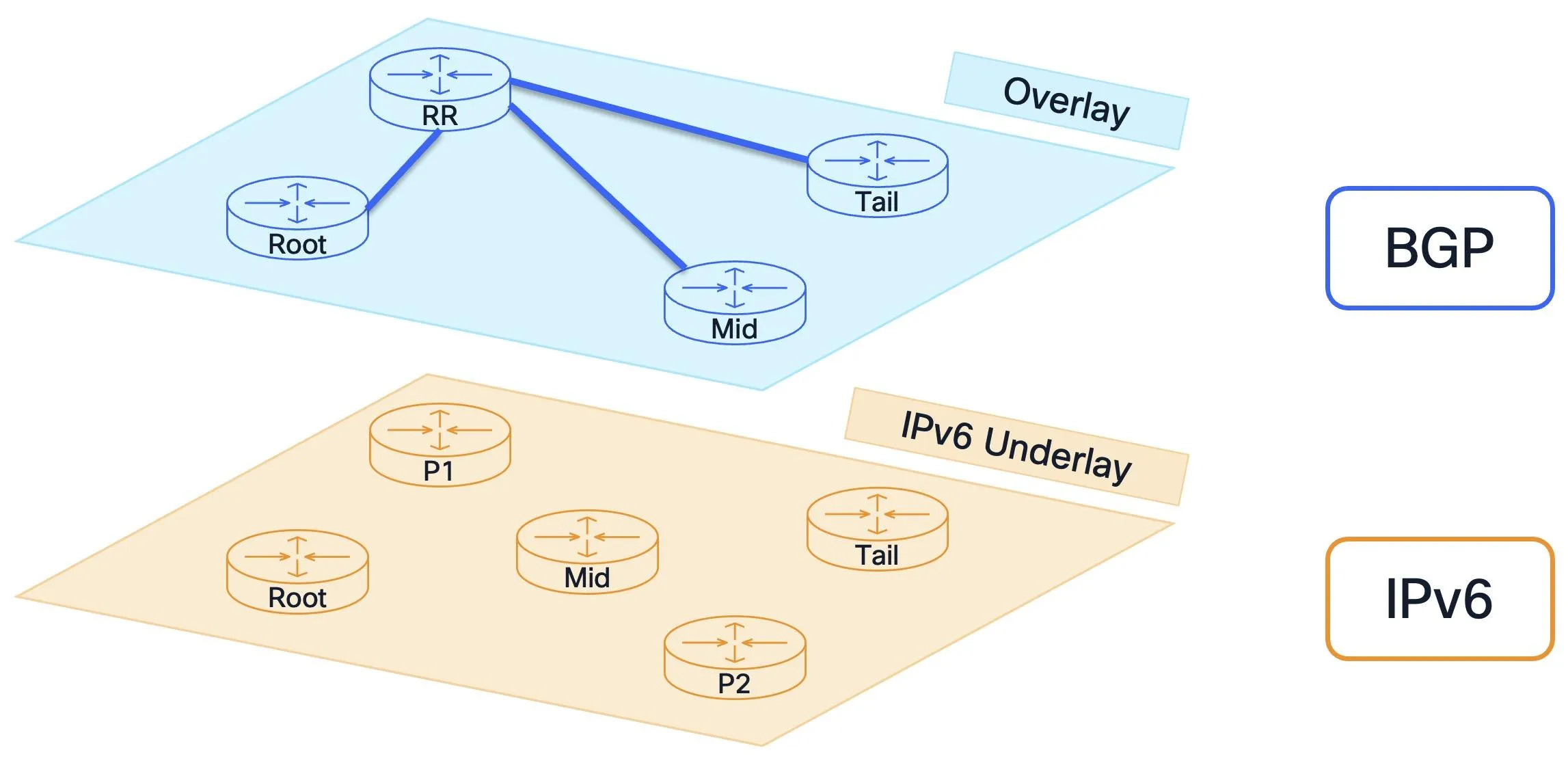
Figure 6: Multicast services over SRv6 / IPv6 cores use a two-plane architecture: BGP MVPN overlay for service signaling and IPv6 underlay with PIMv6-SSM for provider multicast transport.
BGP Overlay Discovery
Using the BGP MVPN Auto-Discovery mechanism introduced earlier, each PE, Root, Mid, and Tail, advertises a Type 1 Intra-AS I-PMSI A-D route via the RR. The Type 1 route carries the PMSI Tunnel Attribute, which specifies the tunnel type, PIM-SSM, the MDT source, the PE loopback, and the MDT group, unique per VRF. At the end of this exchange, all three PEs know each other and know exactly how to build the underlay tree, but no trees are built yet.
PIMv6-SSM Underlay Tree Build
Triggered by the PMSI TA received during overlay discovery, each PE reads the MDT source and group and initiates PIMv6-SSM (S,G) joins toward the other PEs’ loopbacks. These joins propagate hop-by-hop through P1 and P2, the transit routers, and Mid, the bud node acting as both transit hop and PE, building one source-rooted P2MP tree per PE. Collectively, these per-PE trees provide bidirectional PE-to-PE MDT connectivity, while each individual tree remains rooted at a single PE. Transit routers participate in PIM but have no awareness of VPN state. This is pure native IPv6 multicast.
At the end of control plane setup, the provider core has bidirectional PIM trees connecting all PEs, with BGP auto-discovery complete.
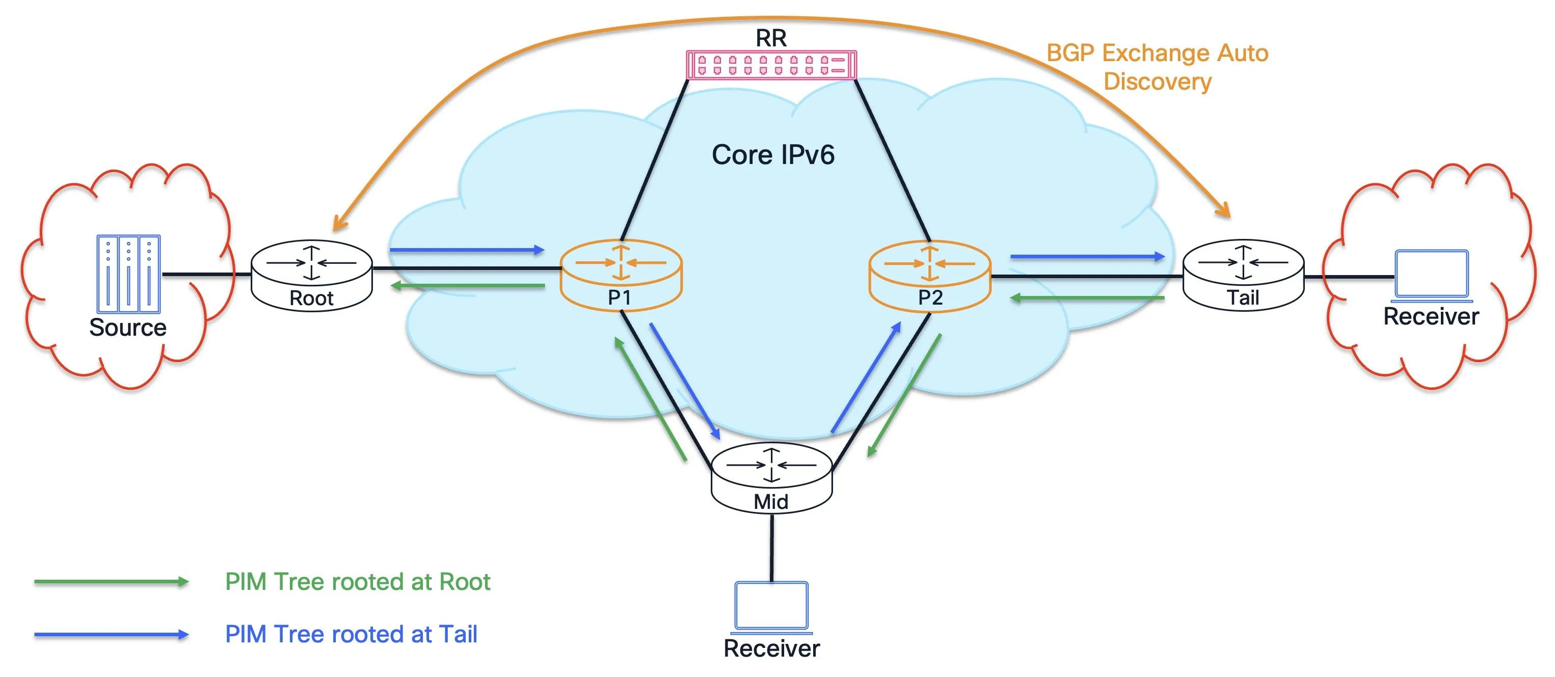
Figure 7: End of control plane setup. BGP exchange auto-discovery connects PEs through the RR, while PIMv6-SSM trees are built in the core.
Customer Join Signaling
When a receiver sends an IGMP/PIM join for a customer (S,G), the egress PE, such as Tail, performs a VRF Reverse Path Forwarding (RPF) lookup pointing to the ingress PE via BGP next-hop, generates a BGP MVPN Type 7 Source Tree Join route, and advertises it to the ingress PE, Root, via the RR. Root programs its VRF entry to forward that customer flow onto the Default MDT. No PIM signaling between PEs is needed, only BGP.
Data Plane
Customer (S,G) traffic arrives at Root, the ingress PE, from the CE, is encapsulated in IP-in-IPv6, and is forwarded onto the PIM-built tree. P1 and P2 forward the packet as native IPv6 multicast and never inspect the inner customer payload. At Tail, the egress PE, the outer header is stripped and the customer packet is delivered to the receiver. PEs maintain both a provider P(S,G) entry and a customer C(S,G) entry; transit routers forward based on P(S,G) only.
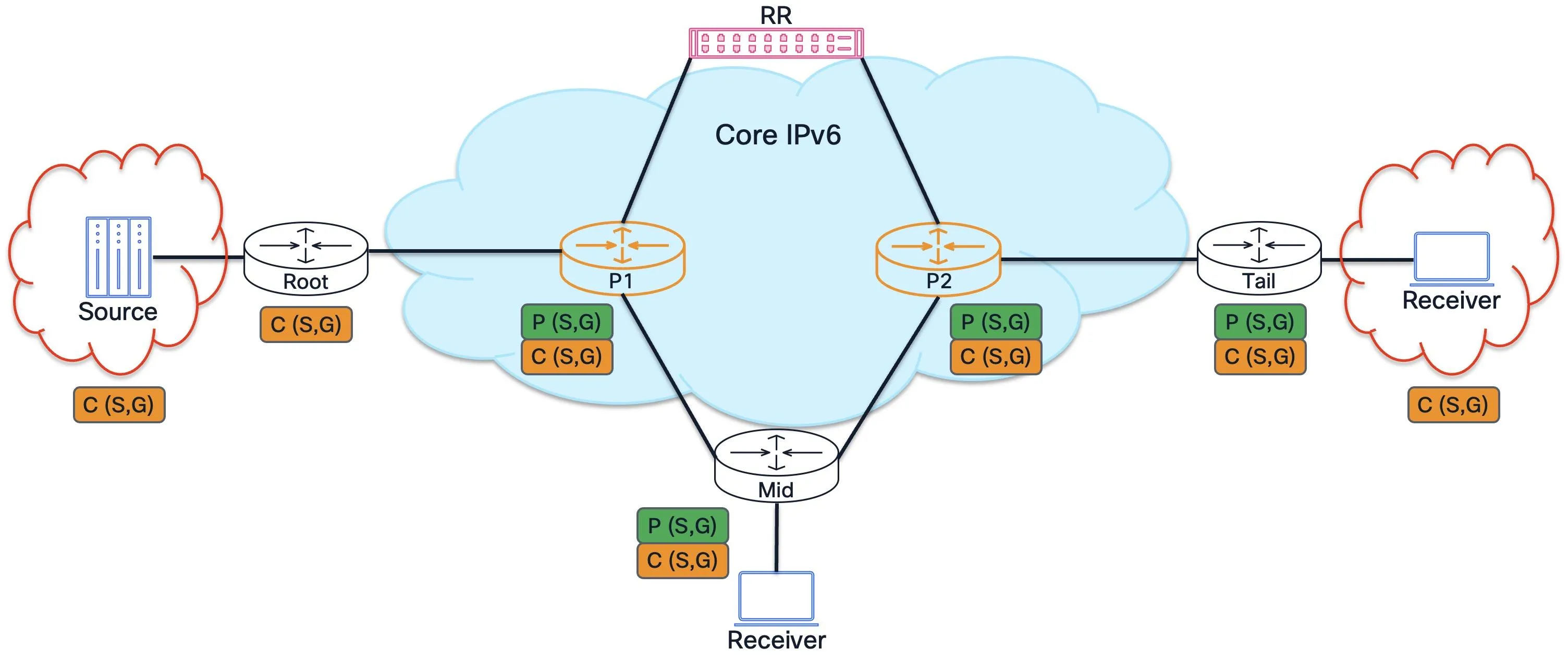
Figure 8: Data plane forwarding with provider P(S,G) state for core IPv6 multicast forwarding and customer C(S,G) state for VRF delivery. Core routers forward natively; only edge PEs perform encapsulation and decapsulation.
The encapsulation is simple IP-in-IPv6, with no GRE, MPLS, or additional tunnel header.

Figure 9: IPv4 customer traffic encapsulation using IP-in-IPv6. The provider IPv6 Next Header field is set to 4 because the inner customer header is IPv4.
At the ingress PE, the customer IPv4 packet is encapsulated in an outer provider IPv6 header; transit routers forward natively; at the egress PE, the outer header is stripped. The Next Header field in the provider IPv6 header must be set to 4, since the customer IP header is an IPv4 header.

Figure 10: IPv6 customer traffic encapsulation using IP-in-IPv6. The provider IPv6 Next Header field is set to 41 because the inner customer header is IPv6.
The IPv6 customer traffic flow is the same, but the inner header is an IPv6 customer header. The Next Header field in the provider IPv6 header must be set to 41, since the customer IP header is an IPv6 header.
Transit P routers require only native IPv6 multicast and PIMv6 support; they forward native IPv6 multicast packets without awareness of the overlay. Only edge PEs require multicast VPN functionality, minimizing the deployment footprint.
Why two protocols? BGP coordinates between PEs, determining who participates with Type 1 routes and who wants what traffic with Type 7 routes. PIM builds the multicast forwarding path through the core routers. Core routers run PIM but never touch BGP MVPN. PEs run both, but for different purposes.
Sample Configuration
The following configuration and verification sections use this reference topology.
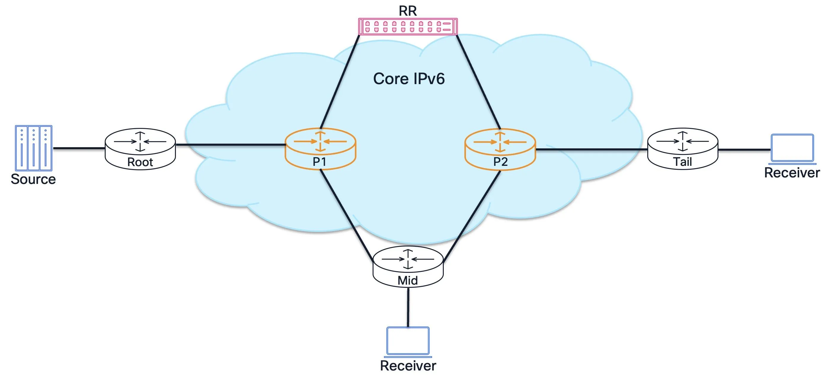
Figure 11: Multicast services over SRv6 / IPv6 cores reference topology. Root is the ingress PE, Mid is a bud-node PE, Tail is the egress PE, P1/P2 are transit routers, and RR is the route reflector.
Root is the ingress/source PE, Mid is a bud-node PE, Tail is an egress/receiver PE, P1/P2 are transit routers, and RR is the route reflector. Attached hosts represent validation traffic endpoints.
| Node | Role | Loopback0 IPv6 | Loopback0 IPv4 |
|---|---|---|---|
| Root | Ingress/source PE | 2001:db8:100::1/128 |
192.0.2.1/32 |
| P1 | Transit P router | 2001:db8:100::2/128 |
192.0.2.2/32 |
| Mid | Bud-node PE | 2001:db8:100::3/128 |
192.0.2.3/32 |
| P2 | Transit P router | 2001:db8:100::4/128 |
192.0.2.4/32 |
| Tail | Receiver/egress PE | 2001:db8:100::5/128 |
192.0.2.5/32 |
| RR | Route Reflector | 2001:db8:100::6/128 |
192.0.2.6/32 |
These snippets cover the multicast-specific components and the BGP address families relevant to the example. IPv6 unicast reachability through the provider core, including IS-IS, SRv6 locators, and Loopback0 reachability, is assumed to be already operational. The SRv6 lines provide the L3VPN service context; the multicast tree remains native IPv6 multicast.
The packet-level validation in this article focuses on an IPv4 customer multicast flow carried over an IPv6 Default MDT:
- Customer source:
198.51.100.100 - Customer group:
232.1.1.1 - VRF:
red - Default MDT group:
ff3e::8000:1
Root Ingress PE
Root uses 2001:db8:100::1, AS 65000, and VRF red.
router bgp 65000
 mvpn
 bgp router-id 192.0.2.1
 address-family ipv4 unicast
!
 address-family vpnv4 unicast
!
 address-family ipv6 unicast
!
 address-family vpnv6 unicast
!
 address-family ipv4 mvpn
!
 address-family ipv6 mvpn
!
 neighbor 2001:db8:100::6
 remote-as 65000
 update-source Loopback0
 address-family vpnv4 unicast
!
 address-family vpnv6 unicast
!
 address-family ipv6 unicast
!
 address-family ipv4 mvpn
!
 address-family ipv6 mvpn
!
!
 vrf red
 rd auto
 address-family ipv4 unicast
 segment-routing srv6
 locator MAIN
 alloc mode per-vrf
!
 redistribute connected
 redistribute static
!
 address-family ipv6 unicast
 segment-routing srv6
 locator MAIN
 alloc mode per-vrf
!
 redistribute connected
!
 address-family ipv4 mvpn
!
 address-family ipv6 mvpn
!
!
router static
 vrf red
 address-family ipv4 unicast
 198.51.100.100/32 198.51.100.1
!
!
!
route-policy rpf-for-srv6-mcast
 set core-tree pim-default-v6
end-policy
multicast-routing
 address-family ipv6
 interface all enable
!
 vrf red
 address-family ipv4
 mdt source ipv6 Loopback0
 interface all enable
 bgp auto-discovery pim6
!
 mdt default ipv6 ff3e::8000:1
!
 address-family ipv6
 mdt source ipv6 Loopback0
 interface all enable
 bgp auto-discovery pim6
!
 mdt default ipv6 ff3e::8000:1
!
!
!
router pim
 address-family ipv6
 interface Loopback0
 enable
!
 interface HundredGigE0/0/0/0
 enable
!
!
 vrf red
 address-family ipv4
 rpf topology route-policy rpf-for-srv6-mcast
 mdt c-multicast-routing bgp
!
 interface HundredGigE0/0/0/2
 enable
!
!
 address-family ipv6
 rpf topology route-policy rpf-for-srv6-mcast
 mdt c-multicast-routing bgp
!
 interface HundredGigE0/0/0/2
 enable
!
!
!
!
The same PE structure applies to Mid, 2001:db8:100::3, and Tail, 2001:db8:100::5; only the loopback addresses, SRv6 locator, BGP router ID, and CE-facing interface differ. In the validation lab, Root redistributes a static route for the IPv4 customer source so receiver PEs have unicast/RPF reachability for 198.51.100.100/32.
Configuration notes:
mdt default ipv6 ff3e::8000:1– The IPv6 SSM group for the Default MDT; each VRF gets a unique group.mdt source ipv6 Loopback0– The PE loopback used as PIM tree source. It must be reachable through the IPv6 underlay.bgp auto-discovery pim6– Enables BGP MVPN auto-discovery with a PIMv6-SSM provider tunnel.rpf topology route-policy rpf-for-srv6-mcast– Directs RPF to use the PIMv6-SSM core tree.mdt c-multicast-routing bgp– Generates MVPN Type 7 routes instead of PIM over MDT for C-multicast state.- PIM is enabled on Loopback0 and all core-facing interfaces, which builds the PIMv6-SSM underlay trees.
address-family ipv4 mvpnandaddress-family ipv6 mvpnare the MVPN address families used in this IOS XR validation. Do not replace them withvpnv4 multicastorvpnv6 multicast.
Route Reflector
The RR uses 2001:db8:100::6 and AS 65000.
router bgp 65000
 mvpn
 bgp router-id 192.0.2.6
 address-family ipv4 unicast
!
 address-family vpnv4 unicast
!
 address-family ipv6 unicast
!
 address-family vpnv6 unicast
!
 address-family ipv4 mvpn
!
 address-family ipv6 mvpn
!
! Root (PE1)
 neighbor 2001:db8:100::1
 remote-as 65000
 update-source Loopback0
 address-family ipv4 unicast
 route-reflector-client
!
 address-family vpnv4 unicast
 route-reflector-client
!
 address-family ipv6 unicast
 route-reflector-client
!
 address-family vpnv6 unicast
 route-reflector-client
!
 address-family ipv4 mvpn
 route-reflector-client
!
 address-family ipv6 mvpn
 route-reflector-client
!
!
! Mid (PE2)
 neighbor 2001:db8:100::3
 remote-as 65000
 update-source Loopback0
 address-family ipv4 unicast
 route-reflector-client
!
 address-family vpnv4 unicast
 route-reflector-client
!
 address-family ipv6 unicast
 route-reflector-client
!
 address-family vpnv6 unicast
 route-reflector-client
!
 address-family ipv4 mvpn
 route-reflector-client
!
 address-family ipv6 mvpn
 route-reflector-client
!
!
! Tail (PE3)
 neighbor 2001:db8:100::5
 remote-as 65000
 update-source Loopback0
 address-family ipv4 unicast
 route-reflector-client
!
 address-family vpnv4 unicast
 route-reflector-client
!
 address-family ipv6 unicast
 route-reflector-client
!
 address-family vpnv6 unicast
 route-reflector-client
!
 address-family ipv4 mvpn
 route-reflector-client
!
 address-family ipv6 mvpn
 route-reflector-client
!
!
!
The RR does not need VRF configuration; it only reflects BGP MVPN routes. All three PEs, Root, Mid, and Tail, are route-reflector-client under ipv4 mvpn and ipv6 mvpn. VPN unicast address families are still needed for customer route reachability.
Transit Routers
P1 uses 2001:db8:100::2; P2 uses 2001:db8:100::4.
multicast-routing
 address-family ipv6
 interface all enable
!
!
router pim
 address-family ipv6
 interface HundredGigE0/0/0/0
 enable
!
 interface HundredGigE0/0/0/1
 enable
!
 interface HundredGigE0/0/0/2
 enable
!
!
!
P routers need only global IPv6 multicast routing and PIMv6 on core-facing interfaces, with no BGP MVPN, no VRF, and no multicast-routing VRF configuration. They forward native IPv6 multicast and propagate PIMv6-SSM joins hop-by-hop with zero awareness of customer VPN state.
PIM is enabled only on the required core-facing interfaces. This avoids activating PIM on unintended links; interface all enable under multicast-routing is retained only as a lab convenience.
Verification
The following verification steps walk through the multicast state layer by layer, matching the order in which the control plane builds up: first BGP MVPN auto-discovery, then provider PIM trees, then customer multicast joins, and finally data-plane forwarding. Run the commands on the indicated routers using the reference topology.
Step 1: BGP MVPN Auto-Discovery
After enabling bgp auto-discovery pim6 on all PEs, each PE originates a Type 1, Intra-AS I-PMSI A-D, route carrying a PMSI Tunnel Attribute that tells remote PEs how to join its Default MDT.
! === Root - verify Type 1 exchange ===
show bgp ipv4 mvpn route-type 1
! Expected: Three Type 1 routes - one local, two received via RR:
! *> [1][2001:db8:100::1]/136
! *>i[1][2001:db8:100::3]/136
! *>i[1][2001:db8:100::5]/136
! The "i" prefix means iBGP-learned; absence means locally originated.
! === RR - verify it reflects all three Type 1 routes ===
show bgp ipv4 mvpn route-type 1
! Expected: All three PE Type 1 routes, each with the originator's loopback as next-hop:
! *>i[1][2001:db8:100::1]/136
! *>i[1][2001:db8:100::3]/136
! *>i[1][2001:db8:100::5]/136
Optionally inspect the PMSI Tunnel Attribute inside a Type 1 route to confirm the underlay tree parameters.
! === Tail - inspect Root's Type 1 detail ===
show bgp ipv4 mvpn [1][2001:db8:100::1]/136 detail
! Key fields to verify in the output:
! PMSI: flags 0x00, type 3 (PIM SSM), label 0
! Originating PE: 2001:db8:100::1
! Multicast Group: ff3e::8000:1
!
! This tells Tail: "To receive Root's MDT traffic, join the PIMv6-SSM tree
! (2001:db8:100::1, ff3e::8000:1)."
! PMSI tunnel type 3 = PIM-SSM. This is separate from BGP MVPN route type 3,
! which is S-PMSI A-D / Data MDT signaling.
Step 2: Provider PIM Trees
Triggered by the PMSI information in Type 1 routes, each PE initiates PIMv6-SSM joins toward the other PEs’ loopbacks for group ff3e::8000:1. Transit routers P1 and P2 forward these joins hop-by-hop with no BGP awareness needed.
! === Root - verify provider PIM trees ===
show pim ipv6 topology ff3e::8000:1
! Expected: P(S,G) entries for the Default MDT group ff3e::8000:1:
!
! (2001:db8:100::1, ff3e::8000:1) SPT - Root's own tree
! RPF: Loopback0,2001:db8:100::1*
! Loopback0 fwd LI LH
! HundredGigE0/0/0/0 fwd Join
!
! (2001:db8:100::5, ff3e::8000:1) SPT - Tail's tree
! RPF: HundredGigE0/0/0/0,fe80::...
! Loopback0 fwd LH MVS MV6S
!
! "MV6S" flag = IPv6 multicast VPN source - indicates this tree feeds the MDT.
! "LI" = local interest, "LH" = last hop.
! === P2 (transit router) - verify hop-by-hop PIM state ===
show pim ipv6 topology ff3e::8000:1
! Expected: P2 is pure transit - no VRF and no MVPN state:
!
! (2001:db8:100::1, ff3e::8000:1) SPT
! RPF: toward Root's direction (HundredGigE0/0/0/0 toward Mid/P1)
! Outgoing: toward Tail (HundredGigE0/0/0/1)
!
! (2001:db8:100::5, ff3e::8000:1) SPT
! RPF: toward Tail's direction (HundredGigE0/0/0/1)
! Outgoing: toward Root/Mid (HundredGigE0/0/0/0)
!
! P2 forwards native IPv6 multicast only.
! === Tail - verify provider PIM trees ===
show pim ipv6 topology ff3e::8000:1
! Expected: Mirror image of Root:
!
! (2001:db8:100::1, ff3e::8000:1) SPT - Root's tree (Tail joined it)
! RPF: toward P2 (incoming from core)
! Loopback0 fwd LH MV6S
!
! (2001:db8:100::5, ff3e::8000:1) SPT - Tail's own tree
! RPF: Loopback0,2001:db8:100::5*
! Loopback0 fwd LI LH
! HundredGigE0/0/0/0 fwd Join
Step 3: Customer Multicast Join
When a receiver sends an IGMP or PIM join for a customer (S,G), the receiver PE creates VRF C(S,G) state and originates a BGP MVPN Type 7 Source Tree Join route. The ingress PE, Root, receives the Type 7 via the RR and starts forwarding customer traffic onto the MDT.
! === Tail - verify VRF customer multicast state after receiver joins ===
show pim vrf red topo 232.1.1.1 198.51.100.100
! Expected for customer flow (198.51.100.100, 232.1.1.1):
!
! (198.51.100.100,232.1.1.1) SPT
! JP: Join(BGP) RPF: mdt6red,2001:db8:100::1
! HundredGigE0/0/0/1 fwd Join(...) LI
!
! KEY INDICATORS:
! "Join(BGP)" - the join was signaled via BGP Type 7, NOT PIM over the MDT.
! "RPF: mdt6red,2001:db8:100::1" - RPF points to Root via the MDT tunnel interface.
! The outgoing interface is toward the CE/receiver.
! === Tail - verify Type 7 route originated locally ===
show bgp ipv4 mvpn route-type 7
! Expected: locally originated Type 7 encoding the customer C-source and C-group:
! *> [7][192.0.2.1:0][65000][32][198.51.100.100][32][232.1.1.1]/184
! 0.0.0.0 0 i
!
! Route encoding: [Type][RD][Source-AS][SrcLen][C-Source][GrpLen][C-Group]
! Next-hop 0.0.0.0 = locally originated.
! === Root - verify VRF customer multicast state after receiving Type 7 ===
show pim vrf red topo 232.1.1.1 198.51.100.100
! Expected:
! (198.51.100.100,232.1.1.1) SPT
! JP: Join(...) RPF: HundredGigE0/0/0/2,198.51.100.1
! mdt6red fwd BGP
!
! KEY INDICATORS:
! "Join(now)" - Root has an active join for this C(S,G).
! "RPF: HundredGigE0/0/0/2,198.51.100.1" - RPF toward the CE/source.
! "mdt6red fwd BGP" - outgoing onto the MDT tunnel, triggered by BGP Type 7.
! === Root - verify Type 7 received from a receiver PE via RR ===
show bgp ipv4 mvpn route-type 7
! Expected: Type 7 received from a receiver PE via RR:
! *>i[7][192.0.2.1:0][65000][32][198.51.100.100][32][232.1.1.1]/184
! 2001:db8:100::3 100 0 i
!
! If both Mid and Tail have active receivers, the RR can learn one Type 7 route
! per receiver PE. The ingress PE installs the selected path or paths according
! to normal BGP best-path and multipath behavior.
Step 4: IPv4 Customer Data Plane
Once the control plane is fully converged, verify that the IPv4 customer multicast traffic is flowing end-to-end over the IPv6 MDT.
In the validation setup, traffic generator and receiver hosts were attached to the PE customer-facing interfaces to prove packet delivery for the IPv4 SSM flow. A traffic source host generated UDP multicast traffic from 198.51.100.100 toward 232.1.1.1. Receiver hosts behind Mid and Tail joined the group and each received the full packet stream. The attached validation hosts are used only to generate and receive customer multicast traffic; they are not part of the provider multicast service architecture.
! === Root - confirm customer traffic is encapsulated onto the MDT ===
show mrib vrf red route 232.1.1.1 198.51.100.100
! Expected: forwarding entry for the customer (S,G) with:
! Incoming interface: HundredGigE0/0/0/2
! Outgoing interface: mdt6red
! === Tail - confirm customer traffic is decapsulated from the MDT ===
show mrib vrf red route 232.1.1.1 198.51.100.100
! Expected: forwarding entry for the customer (S,G) with:
! Incoming interface: mdt6red
! Outgoing interface: HundredGigE0/0/0/1
! === Provider core - confirm native IPv6 MDT state ===
show mrib ipv6 route ff3e::8000:1
! Expected: provider P(S,G) entries for the PE loopbacks and MDT group.
! On transit P routers, the entries should contain only core-facing physical interfaces,
! with no VRF, no BGP MVPN, and no MDT tunnel interface.
Representative validation lab output from the IPv4 packet test:
TrafficSource:
 1000 packets sent from 198.51.100.100 to 232.1.1.1 UDP/5000
MidReceiver:
 1000 packets received
 rx1000 from 198.51.100.100... srv6-mcast seq=1000
TailReceiver:
 1000 packets received
 rx1000 from 198.51.100.100... srv6-mcast seq=1000
Representative PE state while traffic was active:
Root:
 (198.51.100.100,232.1.1.1) SPT
 RPF: HundredGigE0/0/0/2,198.51.100.1
 mdt6red fwd BGP
 Incoming Interface List
 HundredGigE0/0/0/2
 Outgoing Interface List
 mdt6red
Mid:
 (198.51.100.100,232.1.1.1) SPT
 JP: Join(BGP) RPF: mdt6red,2001:db8:100::1
 Incoming Interface List
 mdt6red
 Outgoing Interface List
 HundredGigE0/0/0/2
Tail:
 (198.51.100.100,232.1.1.1) SPT
 JP: Join(BGP) RPF: mdt6red,2001:db8:100::1
 Incoming Interface List
 mdt6red
 Outgoing Interface List
 HundredGigE0/0/0/1
Step 5: IPv6 Customer Data Plane
The same VRF and Default MDT model also carries IPv6 customer multicast traffic. In the validation setup, the IPv6 customer source is 2001:db8:198:51::100, the IPv6 customer SSM group is ff3e::8000:2321, and the traffic is carried in VRF red over the same IPv6 Default MDT group ff3e::8000:1.
Mid and Tail use static MLD receiver state for the IPv6 customer SSM flow:
router mld
 vrf red
 interface HundredGigE0/0/0/2
 static-group ff3e::8000:2321 2001:db8:198:51::100
!
!
!
On Tail, the receiver-facing interface is HundredGigE0/0/0/1; the static group statement is otherwise the same. This creates customer VRF receiver interest for the IPv6 C(S,G), just as IGMP or PIM receiver interest creates customer VRF state for the IPv4 C(S,G).
! === Root - confirm IPv6 customer traffic is encapsulated onto the MDT ===
show pim vrf red ipv6 topology
show mrib vrf red ipv6 route
! Expected: forwarding entry for the IPv6 customer C(S,G) with:
! C-source: 2001:db8:198:51::100
! C-group: ff3e::8000:2321
! Incoming interface: HundredGigE0/0/0/2
! Outgoing interface: mdt6red
! === Mid - confirm IPv6 customer traffic is decapsulated from the MDT ===
show pim vrf red ipv6 topology
show mrib vrf red ipv6 route
! Expected: forwarding entry for the IPv6 customer C(S,G) with:
! Incoming interface: mdt6red
! Outgoing interface: HundredGigE0/0/0/2
! === Tail - confirm IPv6 customer traffic is decapsulated from the MDT ===
show pim vrf red ipv6 topology
show mrib vrf red ipv6 route
! Expected: forwarding entry for the IPv6 customer C(S,G) with:
! Incoming interface: mdt6red
! Outgoing interface: HundredGigE0/0/0/1
Representative validation lab output from the IPv6 packet test:
TrafficSource:
 1000 packets sent from 2001:db8:198:51::100 to ff3e::8000:2321 UDP/5001
MidReceiver:
 1000 packets received
 rx1000 from 2001:db8:198:51::100... srv6-mcast6 seq=1000
TailReceiver:
 1000 packets received
 rx1000 from 2001:db8:198:51::100... srv6-mcast6 seq=1000
Representative IPv6 customer VRF state while traffic was active:
Root:
 (2001:db8:198:51::100,ff3e::8000:2321) SPT
 RPF: HundredGigE0/0/0/2,2001:db8:198:51::1
 mdt6red fwd BGP
 Incoming Interface List
 HundredGigE0/0/0/2
 Outgoing Interface List
 mdt6red
Mid:
 (2001:db8:198:51::100,ff3e::8000:2321) SPT
 JP: Join(BGP) RPF: mdt6red,2001:db8:100::1
 Incoming Interface List
 mdt6red
 Outgoing Interface List
 HundredGigE0/0/0/2
Tail:
 (2001:db8:198:51::100,ff3e::8000:2321) SPT
 JP: Join(BGP) RPF: mdt6red,2001:db8:100::1
 Incoming Interface List
 mdt6red
 Outgoing Interface List
 HundredGigE0/0/0/1
Deployment Considerations
For each multicast-enabled VRF, the initial deployment model uses MDT transport over IPv6 only. Operators transitioning from an IPv4 multicast core should plan for a dedicated migration window rather than a mixed-mode cutover.
Key design considerations:
- Each multicast-enabled VRF should be planned around a single MDT/core transport address family for a given deployment phase.
- Migration from IPv4 GRE-based MDTs to IPv6 IP-in-IP MDTs requires a planned cutover per VRF.
- This article covers single-AS deployments; inter-AS MVPN and extranet multicast are outside the current scope.
- Consult the platform-specific release notes for supported hardware configurations and scale limits.
Future Enhancements
The following capabilities build on the architecture described above and are supported by the underlying standards, but they are not part of the initial deployment model and are planned for subsequent phases. Consult the platform-specific release notes for current availability.
Flex-Algo Integration
Flex-Algo can extend this architecture to influence multicast tree construction in the provider core:
- PIM tree construction can follow Flex-Algo constraint-based paths for latency, affinity, or bandwidth.
- On receiving a multicast subscription for
(S,G), a hop-by-hop tree is built toward the source following the Flex-Algo-defined path. - This enables traffic-engineered multicast without RSVP-TE.
Global Table Multicast
The architecture described above focuses on VRF multicast, where customer traffic is encapsulated in IP-in-IPv6 tunnels across the provider core. However, not all multicast requires VPN isolation.
For multicast in the global routing table, an end-to-end IPv6 core simplifies things further: IPv6 multicast flows natively via PIMv6 without any encapsulation, tunnels, or MDT overlay. This is the simplest deployment model: standard PIMv6-SSM forwarding with no additional machinery.
RFC 7716 extends BGP MVPN procedures to the global table, providing an option to use BGP-based Auto-Discovery and signaling for global table multicast, useful when operators want a consistent BGP MVPN operational model across both VRF and global table multicast.
| Aspect | VRF multicast | Global Table Multicast |
|---|---|---|
| Forwarding context | Per-VRF | Global routing table |
| Encapsulation | IP-in-IPv6 | None, native PIMv6 |
| BGP signaling | Required, MVPN Types 1 and 7 | Optional, RFC 7716 |
| Use case | L3VPN customer multicast | Network-wide multicast without VPN isolation |
In the basic GTM case, multicast forwarding is native IPv6 multicast in the global routing table: no VRF, no route distinguisher, no MDT overlay, and no IP-in-IP encapsulation are used. RFC 7716 defines an optional BGP MVPN-based model for global table multicast. The configuration and verification example in this article focuses on the VRF multicast model using BGP MVPN and IPv6 MDTs.
Conclusion
Cisco’s architecture for multicast services over SRv6 / IPv6 cores uses a two-plane design: BGP MVPN overlay for PE discovery and customer signaling, and PIMv6-SSM underlay for native IPv6 multicast transport, with simple IP-in-IP encapsulation. No SRv6-specific multicast extensions are required.
Key takeaways:
- Standards-based building blocks – Built on RFC 6513/6514 MVPN, RFC 6515/8950 IPv6 underlay signaling support, and RFC 7761 PIM-SM/SSM behavior. No proprietary protocols are in the forwarding path.
- Minimal deployment footprint – Only edge PEs require multicast VPN functionality. Transit P routers need native IPv6 multicast/PIMv6 support, but no VPN awareness.
- Unified transport – The same PIMv6-SSM Default MDT infrastructure carries L3VPN multicast for both IPv4 and IPv6 customer traffic.
- Scalable – Default MDTs provide baseline per-VRF connectivity; Data MDTs deliver bandwidth-efficient selective trees for high-rate flows.
- Room to grow – Flex-Algo traffic engineering and Global Table Multicast are standards-based enhancements planned for subsequent phases.
With growing multi-vendor IETF support, this is the direction Cisco is driving for multicast services over SRv6 / IPv6 cores.
References
| Topic | Link |
|---|---|
| RFC 6513 – Multicast in MPLS/BGP IP VPNs | rfc-editor.org/rfc/rfc6513 |
| RFC 6514 – BGP Encodings and Procedures for Multicast in MPLS/BGP IP VPNs | rfc-editor.org/rfc/rfc6514 |
| RFC 6515 – IPv4 and IPv6 Infrastructure Addresses in BGP Updates for Multicast VPNs | rfc-editor.org/rfc/rfc6515 |
| RFC 7716 – Global Table Multicast with BGP Multicast VPN Procedures | rfc-editor.org/rfc/rfc7716 |
| RFC 8950 – Advertising IPv4 NLRI with an IPv6 Next Hop | rfc-editor.org/rfc/rfc8950 |
| RFC 7761 – Protocol Independent Multicast – Sparse Mode | rfc-editor.org/info/rfc7761 |
| RFC 8402 – Segment Routing Architecture | rfc-editor.org/info/rfc8402 |
| RFC 8986 – Segment Routing over IPv6 Network Programming | rfc-editor.org/info/rfc8986 |
| RFC 9350 – IGP Flexible Algorithm | rfc-editor.org/info/rfc9350 |
| RFC 9502 – IGP Flexible Algorithm in IP Networks | rfc-editor.org/info/rfc9502 |
| Multicast over SRv6 IETF PIM WG draft | datatracker.ietf.org/doc/draft-ietf-pim-multicast-over-srv6 |
| Multicast Distribution Trees on xrdocs | xrdocs.io/multicast/blogs/multicast-distribution-trees-mdts |